

Cotter and Knuckle Joints:
- Introduction : A cotter is a flat wedge shaped piece of rectangular cross-section and its width is tapered (either on one side or both sides) from one end to another for an easy adjustment. The taper varies from 1 in 48 to 1 in 24 and it may be increased up to 1 in 8, if a locking device is provided. The locking device may be a taper pin or a set screw used on the lower end of the cotter. The cotter is usually made of mild steel or wrought iron. A cotter joint is a temporary fastening and is used to connect rigidly two co-axial rods or bars which are subjected to axial tensile or compressive forces. It is usually used in connecting a piston rod to the cross head of a reciprocating steam engine, a piston rod and its extension as a tail or pump rod, strap end of connecting rod
etc. - Types of Cotter Joints : Following are the three commonly used cotter joints to connect two rods by a cotter :
1. Socket and spigot cotter joint 2. Sleeve and cotter joint, and 3. Gib and cotter joint.
-
The design of these types of joints are discussed, in detail, in the following pages.
- Socket and Spigot Cotter Joint
- Design of Socket and Spigot Cotter Joint
- Sleeve and Cotter Joint
- Design of Sleeve and Cotter Joint
- Gib and Cotter Joint
- A Design of Gib and Cotter Joint for Strap End of a Connecting Rod
- Design of Gib and Cotter Joint for Square Rods
- A Design of Cotter Joint to Connect Piston Rod and Cross head
- Design of Cotter Foundation Bolt
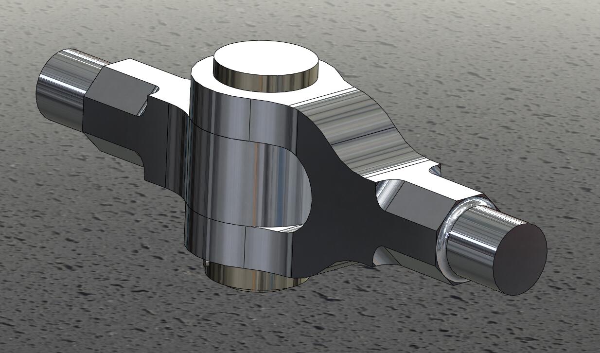
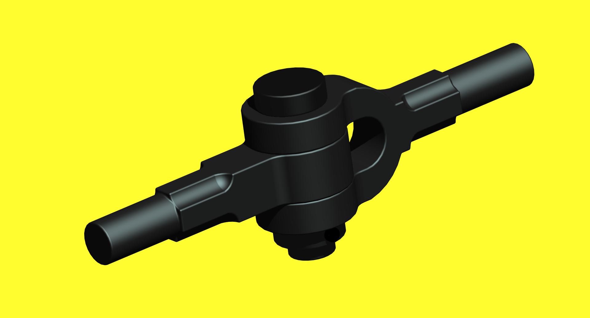
- Knuckle Joint
- Dimensions of Various Parts of the Knuckle Joint
- Methods of Failure of Knuckle Joint
- Design Procedure of Knuckle Joint
- Adjustable Screwed Joint for Round Rods (Turn Buckle).
- Design of Turn Buckle.
Reference A Textbook of a Machine Design by R.S. Khurmi and J.K. Gupta


