

Sleeve and Cotter Joint :
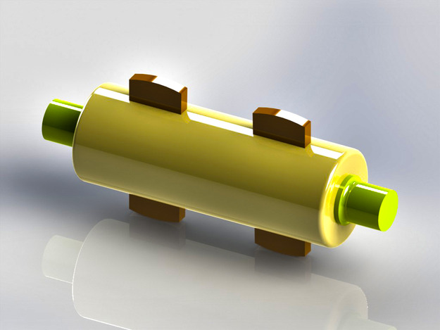
Sometimes, a sleeve and cotter joint as shown in Fig. 1 and 2, is used to connect two round rods or bars. In this type of joint, a sleeve or muff is used over the two rods and then two cotters (one on each rod end) are inserted in the holes provided for them in the sleeve and rods.
The taper of cotter is usually 1 in 24. It may be noted that the taper sides of the two cotters should face each other as shown in Fig. 3. The clearance is so adjusted that when the cotters are driven in, the two rods come closer to each other thus making the joint tight.
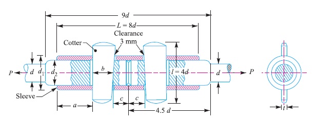
The various proportions for the sleeve and cotter joint in terms of the diameter of rod (d ) are as follows :
Outside diameter of sleeve,
d1 = 2.5 d
Diameter of enlarged end of rod,
d2 = Inside diameter of sleeve = 1.25 d
Length of sleeve, L = 8 d
Thickness of cotter, t = d2/4 or 0.31 d
Width of cotter, b = 1.25 d
Length of cotter, l = 4 d
Distance of the rod end (a) from the beginning to the cotter hole (inside the sleeve end)
= Distance of the rod end (c) from its end to the cotter hole
= 1.25 d
Design of Sleeve and Cotter Joint
The sleeve and cotter joint is shown in Fig. 3.
Let P = Load carried by the rods,
d = Diameter of the rods,
d1 = Outside diameter of sleeve,
d2 = Diameter of the enlarged end of rod,
t = Thickness of cotter,
l = Length of cotter,
b = Width of cotter,
a = Distance of the rod end from the beginning to the cotter hole
(inside the sleeve end),
c = Distance of the rod end from its end to the cotter hole,
σt , τ and σc = Permissible tensile, shear and crushing stresses respectively for the material of the rods and cotter.
The dimensions for a sleeve and cotter joint may be obtained by considering the various modes of failure as discussed below :
1. Failure of the rods in tension
The rods may fail in tension due to the tensile load P. We know that
Area resisting tearing = π d^2 / 4
∴ Tearing strength of the rods = π d^2 σt/ 4
Equating this to load (P), we have
P = π d^2 σt/ 4
From this equation, diameter of the rods (d) may be obtained.
2. Failure of the rod in tension across the weakest section (i.e. slot)
Since the weakest section is that section of the rod which has a slot in it for the cotter, therefore area resisting tearing of the rod across the slot
= π (d2)^2 /4 – d2 t
and tearing strength of the rod across the slot
= [π (d2)^2 /4 – d2 t] σt
Equating this to load (P), we have
P = [π (d2)^2 /4 – d2 t] σt
From this equation, the diameter of enlarged end of the rod (d2) may be obtained.
Note: The thickness of cotter is usually taken as d2 / 4.
3. Failure of the rod or cotter in crushing
We know that the area that resists crushing of a rod or cotter
= d2 × t
∴ Crushing strength = d2 × t × σc
Equating this to load (P), we have
P = d2 × t × σc
From this equation, the induced crushing stress may be checked.
4. Failure of sleeve in tension across the slot
We know that the resisting area of sleeve across the slot
= [π/4{(d1)^2 – (d2)^2}] – (d1 – d2)t
∴ Tearing strength of the sleeve across the slot
= {[π/4{(d1)^2 – (d2)^2}] – (d1 – d2)t} σt
Equating this to load (P), we have
P = {[π/4{(d1)^2 – (d2)^2}] – (d1 – d2)t} σt
From this equation, the outside diameter of sleeve (d1) may be obtained.
5. Failure of cotter in shear
Since the cotter is in double shear, therefore shearing area of the cotter
= 2b × t
and shear strength of the cotter
= 2b × t × τ
Equating this to load (P), we have
P = 2b × t × τ
From this equation, width of cotter (b) may be determined.
6. Failure of rod end in shear
Since the rod end is in double shear, therefore area resisting shear of the rod end
= 2 a × d2
and shear strength of the rod end
= 2 a × d2 × τ
Equating this to load (P), we have
P = 2 a × d2 × τ
From this equation, distance (a) may be determined.
7. Failure of sleeve end in shear
Since the sleeve end is in double shear, therefore the area resisting shear of the sleeve end
= 2 (d1 – d2) c
and shear strength of the sleeve end
= 2 (d1 – d2 ) c × τ
Equating this to load (P), we have
P = 2 (d1 – d2 ) c × τ
From this equation, distance (c) may be determined.
Reference A Textbook of Machine Design by R.S. Khurmi and J.K.Gupta


