
")
Construction of Flywheels
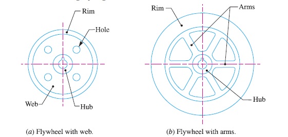
The flywheels of smaller size (upto 600 mm diameter) are casted in one piece. The rim and hub are joined together by means of web as shown in Fig. 2 (a). The holes in the web may be made for handling purposes.
In case the flywheel is of larger size (upto 2.5 metre diameter), the arms are made instead of web, as shown in Fig. 2 (b). The number
of arms depends upon the size of flywheel and its speed of rotation. But the flywheels above 2.5 metre diameter are usually casted in two
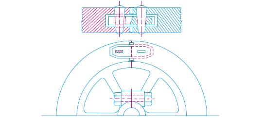
piece. Such a flywheel is known as split flywheel. A split flywheel has the advantage of relieving the shrinkage stresses in the arms due to unequal rate of cooling of casting. A flywheel made in two halves should be spilt at the arms rather than between the arms, in order to obtain better strength of the joint. The two halves of the flywheel are connected by means of bolts through the hub, as shown in Fig. 3. The two halves are also joined at the rim by means of cotter joint (as shown in Fig. 3) or shrink links (as shown in Fig. 4). The width or
depth of the shrink link is taken as 1.25 to 1.35 times the thickness of link. The slot in the rim into which the link is inserted is made slightly larger than the size of link.

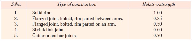
The relative strength of a rim joint and the solid rim are given in the following table.
Reference A Textbook of Machine Design by R.S.Khurmi and J.K.Gupta


 are casted in one piece. The rim and hub are joined togethe)