

Design of Gib and Cotter Joint for Square Rods :
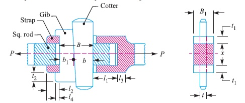
Consider a gib and cotter joint for square rods as shown in Fig. 1. The rods may be subjected to a tensile or compressive load. All components of the joint are assumed to be of the same material.
Let P = Load carried by the rods,
x = Each side of the rod,
B = Total width of gib and cotter,
B1 = Width of the strap,
t = Thickness of cotter,
t1 = Thickness of the strap, and
σt , τ and σc = Permissible tensile, shear and crushing stresses.
In designing a gib and cotter joint, the following modes of failure are considered.
1. Failure of the rod in tension
The rod may fail in tension due to the tensile load P. We know that
Area resisting tearing = x × x = x2
∴ Tearing strength of the rod
= x2 × σt
Equating this to the load (P), we have
P = x2 × σt
From this equation, the side of the square rod (x) may be determined. The other dimensions are fixed as under :
Width of strap, B1 = Side of the square rod = x
Thickness of cotter, t = 1/4 width of strap = B1/4
Thickness of gib = Thickness of cotter (t)
Height (t2) and length of gib head (l4)
= Thickness of cotter (t)
2. Failure of the gib and cotter in shearing
Since the gib and cotter are in double shear, therefore,
Area resisting failure = 2 B × t
and resisting strength = 2 B × t × τ
Equating this to the load (P), we have
P = 2B × t × τ
From this equation, the width of gib and cotter (B) may be obtained. In the joint, as shown in Fig. 3, one gib is used, the proportions of which are
Width of gib, b1 = 0.55 B ; and width of cotter, b = 0.45 B
In case two gibs are used, then
Width of each gib = 0.3 B ; and width of cotter = 0.4 B
3. Failure of the strap end in tension at the location of gib and cotter
Area resisting failure = 2 [B1 × t1 – t1 × t] = 2 [x × t1 – t1 × t] … (Q B1 = x)
∴ Resisting strength = 2 [ x × t1 – t1 × t] σt
Equating this to the load (P), we have
P = 2 [x × t1 – t1 × t] σt
From this equation, the thickness of strap (t1) may be determined.
4. Failure of the strap or gib in crushing
The strap or gib (at the strap hole) may fail due to crushing.
Area resisting failure = 2 t1 × t
∴ Resisting strength = 2 t1 × t × σc
Equating this to the load (P), we have
P = 2 t1 × t × σc
The induced crushing stress may be checked by this equation.
5. Failure of the rod end in shearing
Since the rod is in double shear, therefore
Area resisting failure = 2 l1 × x
∴ Resisting strength = 2 l1 × x × τ
Equating this to the load (P), we have
P = 2 l1 × x × τ
From this equation, the dimension l1 may be determined.
6. Failure of the strap end in shearing
Since the length of rod (l2) is in double shearing, therefore
Area resisting failure = 2 × 2 l2 × t1
∴ Resisting strength = 2 × 2 l2 × t1 × τ
Equating this to the load (P), we have
P = 2 × 2 l2 × t1 × τ
The length of rod (l2) may be determined from this equation. The length l3 of the strap end is proportioned as 2/3 rd of side of the rod. this equation. Usually 3 mm The clearance is kept. The length of cotter is generally taken as 4 times the side of the rod.
Reference A Textbook of Machine Design by R.S. Khurmi and J.K. Gupta


