

Socket and Spigot Cotter Joint :
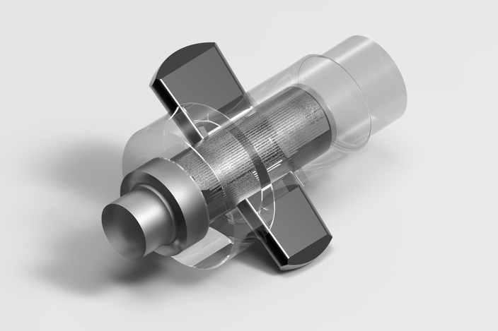
In a socket and spigot cotter joint, one end of the rods (say A) is provided with a socket type of end as shown in Fig. 1 and the other end of the other rod (say B) is inserted into a socket. The end
of the rod which goes into a socket is also called spigot. A rectangular hole is made in the socket and spigot. A cotter is then driven tightly through a hole in order to make the temporary connection between the two rods. The load is usually acting axially, but it changes its direction and hence the cotter joint must be designed to carry both the tensile and compressive loads. The compressive load is taken up by the collar on the spigot.
Design of Socket and Spigot Cotter Joint :
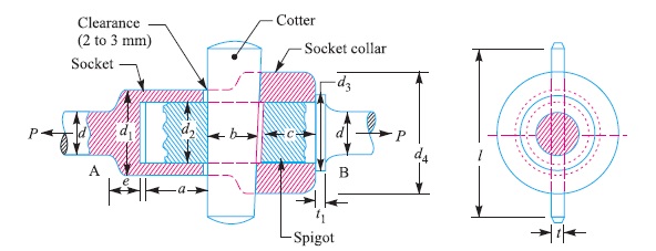
The socket and spigot cotter joint is shown in Fig. 1.
Let P = Load carried by the rods,
d = Diameter of the rods,
d1 = Outside diameter of socket,
d2 = Diameter of spigot or inside diameter of socket,
d3 = Outside diameter of spigot collar,
t1 = Thickness of spigot collar,
d4 = Diameter of socket collar,
c = Thickness of socket collar,
b = Mean width of cotter,
t = Thickness of cotter,
l = Length of cotter,
a = Distance from the end of the slot to the end of rod,
σt = Permissible tensile stress for the rods material,
τ = Permissible shear stress for the cotter material, and
σc = Permissible crushing stress for the cotter material.
The dimensions for a socket and spigot cotter joint may be obtained by considering the various modes of failure as discussed below :
1. Failure of the rods in tension
The rods may fail in tension due to the tensile load P. We know that
Area resisting tearing
= π × d^2 / 4
∴ Tearing strength of the rods,
= π × d^2 × σt/ 4
Equating this to load (P), we have
P = π × d^2 × σt/ 4
From this equation, diameter of the rods ( d ) may be determined.
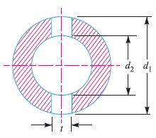
2. Failure of spigot in tension across the weakest section (or slot)
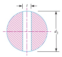
Since the weakest section of the spigot is that section which has a slot in it for the cotter, as shown in Fig. 2, therefore
Area resisting tearing of the spigot across the slot
= π (d2)^2 – d2×t
and tearing strength of the spigot across the slot
= [π (d2)^2 – d2×t] σt
Equating this to load (P), we have
P = [π (d2)^2 – d2×t] σt
From this equation, the diameter of spigot or inside diameter of socket (d2) may be determined.
Note : In actual practice, the thickness of cotter is usually taken as d2 / 4.
3. Failure of the rod or cotter in crushing
We know that the area that resists crushing of a rod or cotter
=d2 × t
∴ Crushing strength = d2 × t × σc
Equating this to load (P), we have
P =d2 × t × σc
From this equation, the induced crushing stress may be checked.
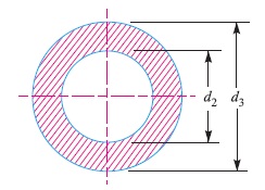
4. Failure of the socket in tension across the slot
We know that the resisting area of the socket across the slot, as shown in Fig. 3
= π/4 [(d1)^2 – (d2)^2] – (d1 – d2)t
∴ Tearing strength of the socket across the slot
= { π/4 [(d1)^2 – (d2)^2] – (d1 – d2)t } σt
Equating this to load (P), we have
P = { π/4 [(d1)^2 – (d2)^2] – (d1 – d2)t } σt
From this equation, outside diameter of socket (d1) may be determined.
5. Failure of cotter in shear
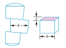
Considering the failure of cotter in shear as shown in Fig. 4. Since the cotter is in double shear, therefore shearing area of the cotter
= 2 b × t
and shearing strength of the cotter
=2 b × t × τ
Equating this to load (P), we have
P =2 b × t × τ
From this equation, width of cotter (b) is determined.
6. Failure of the socket collar in crushing
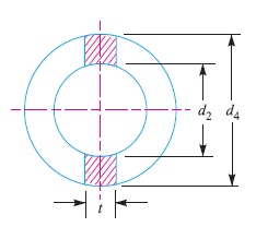
Considering the failure of socket collar in crushing as shown in
Fig. 5
We know that area that resists crushing of socket collar
=(d4 – d2) t
and crushing strength =(d4 – d2) t × σc
Equating this to load (P), we have
P =(d4 – d2) t × σc
From this equation, the diameter of socket collar (d4) may be obtained.
7. Failure of socket end in shearing
Since the socket end is in double shear, therefore area that resists shearing of socket collar
=2 (d4 – d2) c
and shearing strength of socket collar
=2 (d4 – d2) c × τ
Equating this to load (P), we have
P =2 (d4 – d2) c × τ
From this equation, the thickness of socket collar (c) may be obtained.
8. Failure of rod end in shear
Since the rod end is in double shear, therefore the area resisting shear of the rod end
= 2 a × d2
and shear strength of the rod end
= 2 a × d2 × τ
Equating this to load (P), we have
P = 2 a × d2 × τ
From this equation, the distance from the end of the slot to the end of the rod (a) may be obtained.
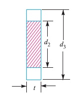
9. Failure of spigot collar in crushing
Considering the failure of the spigot collar in crushing as shown in Fig. 6. We know that area that resists crushing of the collar
= π/4 [(d3)^2 – (d2)^2]
and crushing strength of the collar
= π/4 [(d3)^2 – (d2)^2] σc
Equating this to load (P), we have
P = π/4 [(d3)^2 – (d2)^2] σc
From this equation, the diameter of the spigot collar (d3) may be obtained.
10. Failure of the spigot collar in shearing
Considering the failure of the spigot collar in shearing as shown in Fig. 12.7. We know that area that resists shearing of the collar
= π d2 × t1
and shearing strength of the collar,
= π d2 × t1 × τ
Equating this to load (P) we have
P = π d2 × t1 × τ
From this equation, the thickness of spigot collar (t1) may be obtained.
11. Failure of cotter in bending
In all the above relations, it is assumed that the load is uniformly distributed over the various cross-sections of the joint. But in actual
practice, this does not happen and the cotter is subjected to bending. In order to find out the bending stress induced, it is assumed that the load on the cotter in the rod end is uniformly distributed while in the socket end it varies from zero at the outer diameter (d4) and maximum at the inner diameter (d2), as shown in Fig. 8.
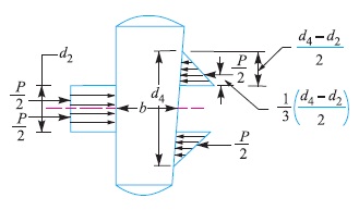
The maximum bending moment occurs at the centre of the cotter and is given by
Mmax = P/2 [1/3 × (d4 – d2)/2 × d2/2] – [P/2 × d2/4]
= P/2 [(d4 – d2)/6 + (d2/2) – (d2/4)]
= P/2 [(d4 – d2)/6 + (d2/4)]
We know that section modulus of the cotter,
Z = t × b^2 / 6
∴ Bending stress induced in the cotter,
σb = Mmax / Z
= P/2 [(d4 – d2)/6 + (d2/4)] / [t × b^2 / 6]
= P (d4 + 0.5d2) / 2t × b^2
This bending stress induced in the cotter should be less than the allowable bending stress of the cotter.
12.The length of cotter (l) is taken as 4 d.
13. The taper in cotter should not exceed 1 in 24. In case the greater taper is required, then a locking device must be provided.
14.The draw of cotter is generally taken as 2 to 3 mm.
Notes:
1. When all the parts of the joint are made of steel, the following proportions in terms of diameter of the rod (d) are generally adopted :
d1 = 1.75 d , d2 = 1.21 d , d3 = 1.5 d , d4 = 2.4 d , a = c = 0.75 d , b = 1.3 d, l = 4 d , t = 0.31 d , t1 = 0.45 d , e = 1.2 d.
Taper of cotter = 1 in 25, and draw of cotter = 2 to 3 mm.
2. If the rod and cotter are made of steel or wrought iron, then τ = 0.8 σt and σc = 2 σt may be taken.
Reference A Textbook of Machine Design by R.S. Khurmi and J.K. Gupta


 is provided with a socket type of end as..)