

Interface Buzzer with LPC2148
A buzzer or beeper is an audio signal generator typedevice, which may be mechanical, electromechanical or piezoelectric depending upon the operating principle of the device. Buzzers are widely used in alarm devices, timers and confirmation of user input such as a mouse click or keystroke.
In embedded systems, buzzer is widely used to notify various events such as interrupt generation, end of any process or as an alarming on emergency situation such as detection of fire, exceeding radiation in nuclear reactor plant etc.
This section aims to explain how to interface buzzer with LPC 2148.
[nextpage title=”Description” ]In embedded system applications, buzzer is interfaced with micro-controller and alarming signal is generated. On micro-controller pin, controlling signal is generated by means of programming. Buzzers operating at 5V are widely available. But LPC2148 operates at 3.3V. So we need a buck converter which will convert 3.3V into 5V.
To designthe driver circuit, we have following options.
1. Transistor as a switch
2. Use of audio amplifier in designing the driver
Let us study how we can design circuits for above options.
1. Transistor as a switch
Introduction to BIPOLAR JUNCTION TRANSITORS- BJT
BJT is designed by sandwiching one layer of P or N type by two layers of opposite type. Depending upon the construction, there as two types available, NPN and PNP.
Three sections of BJTs are known as BASE, EMITTER and COLLECTOR.
BJT operates in three regions.
1. Cut-off Region
2. Saturation region
3. Linear region
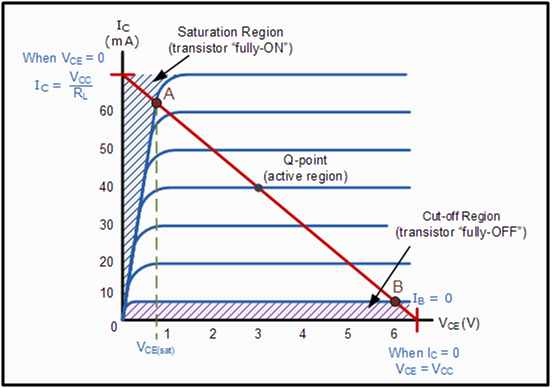
We can configure BJT to operate in any of the above region by proper biasing.
When operated in LINEAR or ACTIVE region, BJT works as an amplifier. To use BJT as a switch, we have to configure it to operate in cut off and saturation region. In cut off region, IDEAL BJT acts as OPEN circuit and in saturation region it acts as short circuit.
Practical BJT offers very high resistance in cut off region and very low resistance in saturation region.
Circuit to bias BJT as a switch is as shown in figure.
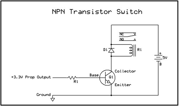
Here Relay is used as LOAD. Any load like MOTOR, BUZZER etc. can be operated by relay. D1 is fly back diode which is must while operating coil based device such as relay and motor to prevent back EMF generated during operation.
Following table explains the working of above circuit.
| INPUT | BJT OPERATIONAL REGION | BJT ACTS AS | OUTPUT |
| 0 Volt | Cut off | Open circuit | Load is disconnected |
| 3.3 Volt | Saturation | Short Circuit | Load is connected |
From the above table, it is clear that when we will put logic 1 on pin of LPC 2148, buzzer will sound and logic 0 on pin stops the buzzing sound from buzzer.
Disadvantages:
Above described system offers following disadvantages.
1. When BJT is not in complete OFF stage, it will create low intensity sound.
2. Stability of above circuit is not very high. Variation in atmosphere, components value and aging effect on components may affect the working of the system.
Considering above factors, we have another mechanism in which we will use comparator IC for better reliability and stability as explained below.
Schematic for this is as shown below:
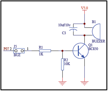
2. Use of Audio amplifier to design driver circuit
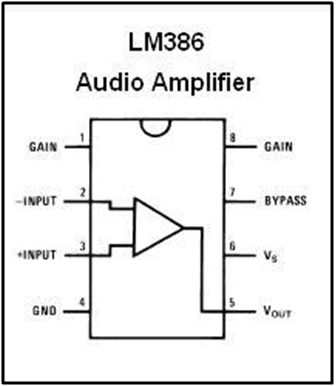
LM386 is specially designed audio amplifier IC. Pin configuration of LM 386 is as follows.It operates in differential mode and amplifies the difference between two input signals on pin 3 and pin 2. Gain of this amplifier is controlled by pin 8.
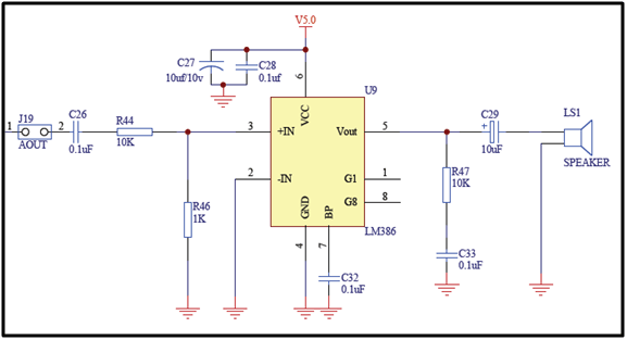
LM386 has been configured in such a way that when we will provide logic 1on P0.8 pin, buzzer will make sound. Buzzer of 8 ohm input impedance is best suitable for this application.
Once the above connections are done, let us start with programming.
Follow the given steps.
1. Make P0.7 to operate as GPIO pin using PINSEL.
2. Configure PO.7 as output pin using IO0DIR.
3. Provide signals on P0.7 to control buzzing sound from buzzer.
We have provided a time varying control signals to demonstrate the generation of various frequency tones from buzzer. At the same time we are flashing LEDs connected at P1.16-P1.23 so that we can see effect of varying frequency.
[/nextpage][nextpage title="Code" ]#include<lpc21xx.h>
void delay(unsigned long cnt)

{
            unsigned long temp,val;

            for(temp=0;temp<cnt;temp++)

            for (val=0;val<10;val++);
}

int main(void)

 {
            unsigned int i;

            IO0DIR = 0Xffffffff;

            IO1DIR=0Xffffffff;

            while(1)

            {
                        for (i=0;i<10000;i=i+100)

                        {
                                    IO0SET = 0X00000080;

                                    IO1SET = 0X00ff0000;

                                    delay(i*10);

                                    IO0CLR = 0X00000080;

                                    IO1CLR = 0X00ff0000;

                                    delay(i*10);

                        }

                        for (i=10000;i>0;i=i-100)

                        {

                                    IO0SET = 0X00000080;

                                    IO1SET = 0X00ff0000;

                                    delay(i*10);

                                    IO0CLR = 0X00000080;

                                    IO1CLR = 0X00ff0000;

                                    delay(i*10);

                        }

            }

}[/nextpage]


