

Interface SD Card with Arduino
[nextpage title=”Summary” ]The microcontroller systems may have to back up the data which they have read during their operation or the data which they need to access during their running time. Most of the microcontrollers have built-in EEPROM memory but they come in comparatively small sizes. In order to use the microcontroller in applications like file accessing, media player etc. an external memory card is necessary.
The SD memory card comes in large storage capacities ranging from 1 GB to 8 GB and they are compatible with the SPI bus of the microcontroller. The large storage capacity and simplicity in interfacing results in wide usage of SD memory card by the microcontrollers. The files in an SD memory card are stored using FAT32 or FAT16 and one should use the code or FAT file-system library to access the files from an SD card.
The easy prototyping platform Arduino provides a library for accessing the SD memory cards. This particular project explains how to interface a SD card using an Arduino board and perform some read and write operations on it.
 [/nextpage][nextpage title=”Description” ] Description
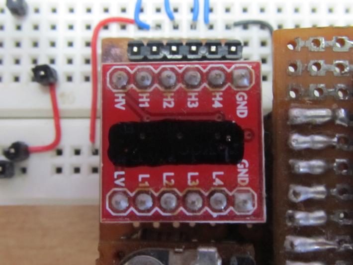
The memory card used in this particular project is a 2 GB SD card from Transcend but the code is supposed to work with SD card from all vendors. The SD card operates on 3.3V logic and hence to interface it with a microcontroller which runs on 5V logic one should use a Logic Level Converter. The image of the Logic Level Converter module used in this project is shown in the following image;
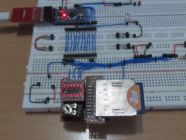
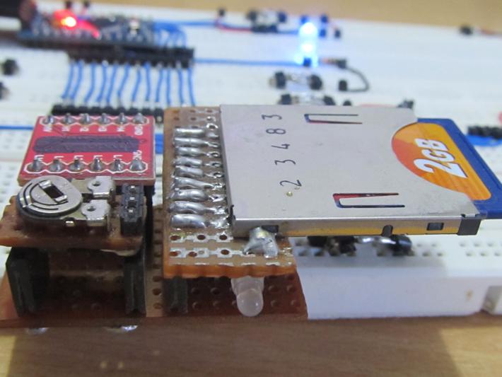
 The SD memory card and the low voltage side of the Logic Level Converter should be provided with the 3.3V power supply and for that one can use any 3.3V regulator IC. A bi-color LED is suggested to connect across the 3.3V positive and MISO and MOSI lines of the SD card. The image of the memory card and the required circuitry that has been built for this particular project is shown in the following image. In the image one can see a potentiometer which is actually forms the circuit with an SMD variable regulator IC LM117 underneath it. It is recommended to use LM1117 which is a 3.3V regulator and which does not require other components to set the voltage as shown in the circuit diagram of this project.
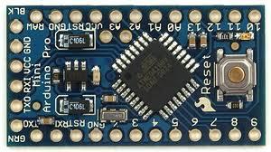
 The Arduino pro-mini board has digital pins marked as 2, 3, 4 up to 13. Among the digital pins four pins namely 10, 11, 12 and 13 can be configured as SS, MOSI, MISO and SCK. The MISO of the memory card should be connected to the pin number 11 The MOSI should be connected to the pin number 12 and the SCK should be connected to the pin number 13 of the Arduino pro-min, The SS of the SD card should be connected to the pin which is defined as the SS pin of the Arduino in the code written The image of the Arduino pro-mini board and the Arduino IDE version 1.0.3 for windows used in this project are shown in the following image;
 Since the arduino pro-mini board has no circuitary for interfacing it with the serial port or the USB port of the PC, an external USB to TTL converter board is required to connect it with the PC. This hardware helps in programming the arduino board and also helps in the serial communication with the PC through the USB port of the


