

Introduction:
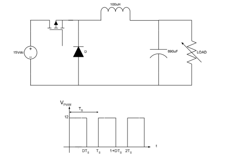
DC-DC choppers can be controlled via PWM signal and output 9V-12V-20V, this signal voltage up to 60V MOSFET can control the output voltage will be based. This circuit has been checked 5V. DC-DC chopper circuit 1 mosfet, 1 diode, 1 coil consists of 1 capacitor.
TYPE OF CIRCUIT:
MATERIALS TIME:
1 MOSFET (IRF540)
1 package (100uh)
1 capacitor (0.1mf)
1 diode
1 Arduino (error “0” will produce a PWM signal loopback to be done and I)
1 op-amp (741) (to be used as a comparator)
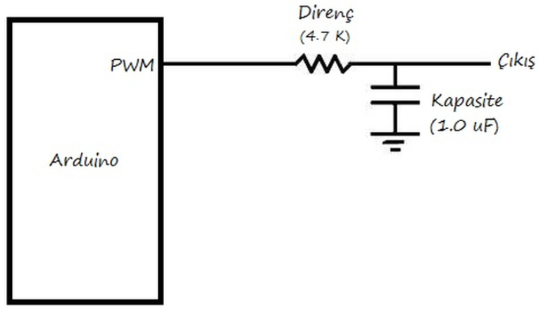
1 10uF capacitor and resistor 4.7km (They are used as a filter for the PWM output of the opamp output that can be measured and will enter A0 analog input.)
PRINCIPLE OF OPERATION CIRCUIT AND OPERATING MODES:
MOSFET according to the shape of the above depends on the DC power source at one end. When we want to run this resource so MOSFET PWM output with 50% of our control, we see half of these resources. The limitation of this resource gap should be in power MOSFETs can carry. Typically 60 V up to a MOSFET power switches. The switching of the MOSFET is the PWM signal will produce any environment. We have been able to help our Arduino PWM signal. Here you can learn about the PWM signal. Let’s give information about the operating mode to examine the operation of the circuit after finishing the general expression of the circuit.
Operating modes:
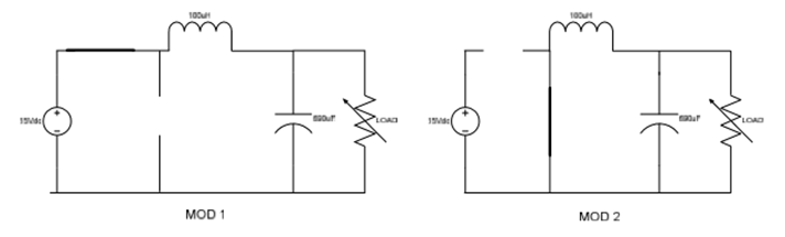
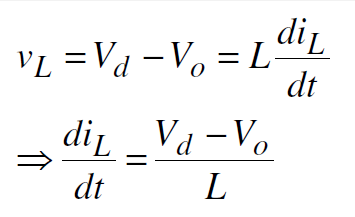
Mode conditions are such as to explain the switching MOSFET turns. Mode 1 switch is off. And in this case the inductor (coil) is connected directly between the input and output. This voltage in the coil end of the case is the difference between the input voltage and output voltage.
VL = Vd-V0
Mode 2 the MOSFET diode in transmission segment. In this case, the coil is equal and opposite to the output voltage poleritel we observe a voltage. That is a return of the coil bobbin reverse.
VL = -V0
From here;
1.Mo you if we formulate equations;
2.Mo you if we formulate equations;
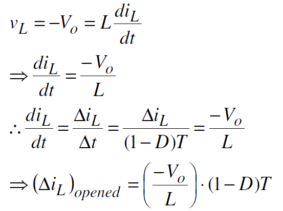
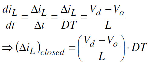
The net change in inductor current is 0 in a circuit switching time period has reached a steady state. Hence;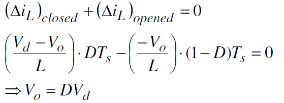
Recent shows us that we have obtained equation input voltage (Vd) duty cycle (D), then the changing so we want by changing the PWM signal output voltage (V0) can be obtained. D is working as humiliating for this circuit will be between 0-1.
THE ARDUINO CONNECTION METHOD OF CIRCUIT
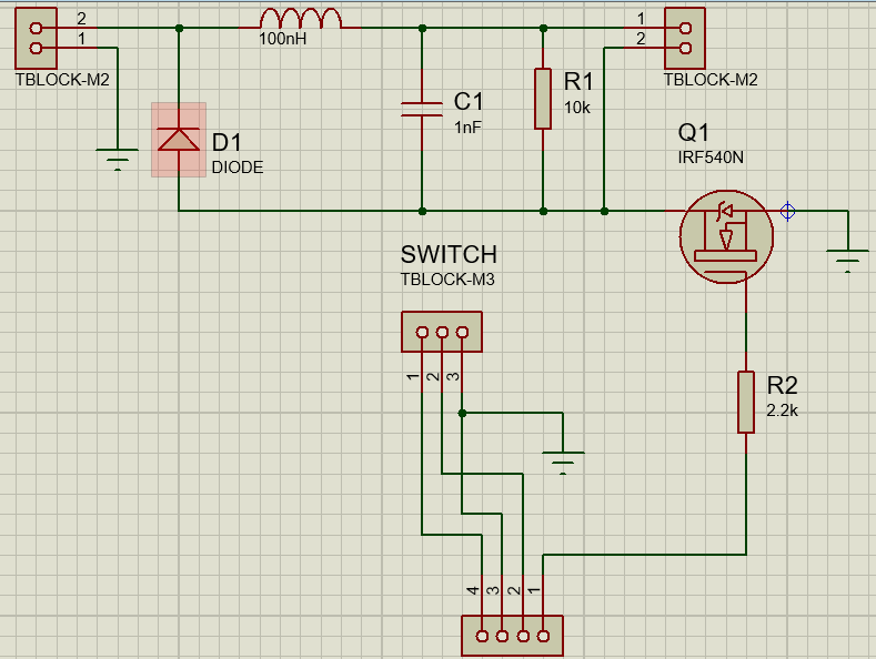
I used my own circuit switch here but would also not used so we take into account that he enter the pin 2 pin. 1.p is Arduino’s PWM output. 3 and 4 there is no need to consider the pinleri is used only for switching. So here we give the Arduino’s PWM output MOSFET Gheit. We will control the left side clamps no input voltage is up to the person using that we will check how many volts of power. The clamps no on the right side is our exit.
OP-AMP circuit Remover:
This was used to detect I Gereli our circuit output terminals. Out of our voltage analog input can not be directly entered into the Arduino. Because it is necessary to enter a single entry. This op-amp in “+” exit 1 end to the other end to end with little potential “-” in between we will find potential link at the end. So our exit is situated 3 V + 5V at the other end of the klamen get 1 + 2V 2 tip. Because the values I want to measure my 3 volts was used to find it.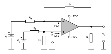
Wherein all of the values of resistance must be the same.
OP-AMP INTERIOR: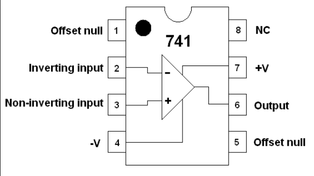
Placing low-pass filter the Arduino out:
The purpose of this circuit is used in case of measuring any PWM signal. Simple and a circuit widely used. The aim is smoothing the signal by removing the high frequency signal with.
Arduino code and purpose:
This Arduino circuit this error by producing a new PWM value of the measured error of the objective of this undesired error signal is used to achieve results that make junk. For example, 50% according to this signal to our circuit we apply a PWM signal at the output of 5 V may If the input signal has 2.5 like we’ll see an error signal. However, this may not be the case. Close to 3 volts output we get this error “0” s purpose to realize a control system is required. In the control system signals between 0-1024 understood and taught error signal is interfering with the PWM signal at this value. A PWM signal of 75% was applied in this program. We put OP-AMP signal from the lowpass filter ‘s output analog inputs (A0), we’re putting. Here we read a value corresponding to 75% PWM (0-1024), we compared with 732. We do this intervention error that is the difference between the value of the PWM signal with up to VALUES.
Arduino code:
#include<LiquidCrystal.h>LiquidCrystal LCD(11,10,2,3,4,6);float deger=732;double deger10=0,hata;int sensorValue = 0;int sensorValue1 = 0;int x=0,a=2;void setup() {// put your setup code here, to run once:Serial.begin(9600);pinMode(5,OUTPUT);LCD.begin(16, 2);}long int y = millis();void loop() {// put your main code here, to run repeatedly:if ( millis() - y >= 10000) {while(a==2){sensorValue = analogRead(A0);sensorValue1 = 1023;Serial.println( sensorValue);Serial.println(sensorValue1);deger10=(sensorValue);hata=deger-deger10;x=hata;Serial.println(x);y = millis();a=3;float voltaj = ( ((float)analogRead(A0)+x) * 5.0 / 1024.0);LCD.setCursor(0,1);LCD.print(" ");LCD.print("voltaj:");LCD.print(voltaj);LCD.setCursor(0,1);}}digitalWrite(5,HIGH);delayMicroseconds(deger+x);digitalWrite(5,LOW);delayMicroseconds((1023-deger)-x);}


