
Flange Coupling
A flange coupling usually applies to a coupling having two separate cast iron flanges. Each flange is mounted on the shaft end and keyed to it. The faces are turned up at right angle to the axis of the shaft. One of the flange has a projected portion and the other flange has a corresponding recess.


This helps to bring the shafts into line and to maintain alignment. The two flanges are coupled together by means of bolts and nuts. The flange coupling is adopted to heavy loads and hence it is used on large shafting.
The flange couplings are of the following three types :
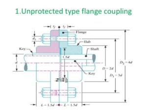
1. Unprotected type flange coupling.
In an unprotected type flange coupling, as shown in Fig. 4, each shaft is keyed to the boss of a flange with a counter sunk key and the flanges are coupled together by means of bolts. Generally, three, four or six bolts are used. The keys
are staggered at right angle along the circumference of the shafts in order to divide the weakening effect caused by keyways.
The usual proportions for an unprotected type cast iron flange couplings, as shown in Fig. 4, are as follows :
If d is the diameter of the shaft or inner diameter of the hub, then
Outside diameter of hub,
D = 2 d
Length of hub, L = 1.5 d
Pitch circle diameter of bolts,
D1 = 3d
Outside diameter of flange,
D2 = D1 + (D1 – D) = 2 D1 – D = 4 d
Thickness of flange, tf = 0.5 d
Number of bolts = 3, for d upto 40 mm
= 4, for d upto 100 mm
= 6, for d upto 180 mm
2. Protected type flange coupling.
In a protected type flange coupling, as shown in Fig. 5, the protruding bolts and nuts are protected by flanges on the two halves of the coupling, in order to avoid danger to the workman.
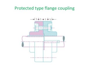
The thickness of the protective circumferential flange (tp) is taken as 0.25 d. The other proportions of the coupling are same as for unprotected type flange coupling.
3. Marine type flange coupling.
In a marine type flange coupling, the flanges are forged integral with the shafts as shown in Fig. 13.14. The flanges are held together by means of tapered headless bolts, numbering from four to twelve depending upon the diameter of shaft.
The number of bolts may be choosen from the following table.
![Number of bolts for marine type flange coupling. [According to IS : 3653 – 1966 (Reaffirmed 1990)]](https://www.engineersgallery.com/wp-content/uploads/2015/10/26.jpg)
Thickness of flange = d / 3
Taper of bolt = 1 in 20 to 1 in 40
Pitch circle diameter of bolts, D1 = 1.6 d
Outside diameter of flange, D2 = 2.2 d

References A Textbook of a Machine Design by R. S. Khurmi and J. K. Gupta


