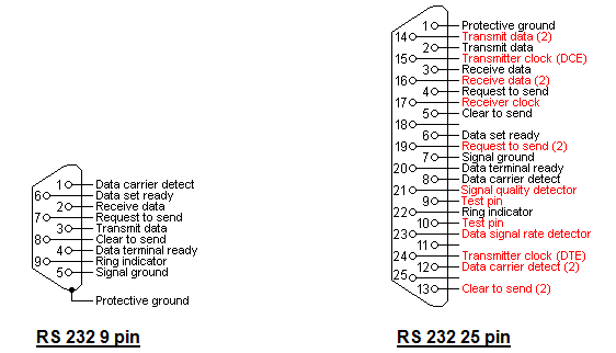
Before Universal Serial Bus (USB) in computers RS232 (serial cable) was used as a standard port for communication between different devices like printers, mouse, modems and all other type of computer peripherals and the computer. In terms of definition, RS232 can be defined as point to point communication between the Data Terminal Equipment (DTE) and Data Communication Equipment (DCE). On RS 232, 920 Kbps of data speed is achievable and the fact that it is called a serial port is that it transfers data bit by bit. RS232 comes in two different variants of D-style 9 pin and 25 pin the former is called as DB 9 connector and the later is called as DB 25 connector, however only three pins are required for communication.
Other pins present in RS 232 port are used depending upon the peripheral support. Devices like Modem utilize all the pins to achieve full handshaking capabilities. For having reliable communication, the length of cable used should be less than 50 ft. set to 9600 baud rate. To have a communication over long distance, other resources like wireless communication can also be used. Before 1997 the RS232 was termed as EIA232F, where EIA stands for “Electronic Industries Association” were it was developed but after the renewal of standards its name was replaced with RS232.
Related Article :
WIRELESS RF-ID ATTENDANCE SYSTEM BASED ON ZIGBEE TECHNOLOGY
ARM-7 BASED SEMI AUTONOMOUS VEHICLE
How to Generate a Variable Frequency Sine Wave Using Arduino
Pin Configuration:
The pin configuration and signaling taking place in RS232 is tabulated below:
|
DB 9
|
DB 25
|
Acronym
|
Full name
|
Direction
|
|
Pin 3
|
Pin 2
|
TXD
|
Transmit Data
|
out
|
|
Pin 2
|
Pin 3
|
RXD
|
Receive Data
|
in
|
|
Pin 7
|
Pin 4
|
RTS
|
Ready to send
|
out
|
|
Pin 8
|
Pin 5
|
CTS
|
Clear to send
|
in
|
|
Pin 6
|
Pin 6
|
DSR
|
Data set Ready
|
In
|
|
Pin 4
|
Pin 20
|
DTR
|
Data terminal Ready
|
out
|
|
Pin 1
|
Pin 8
|
DCD
|
Data Carrier Detect
|
in
|
|
Pin 9
|
Pin 22
|
RI
|
Ring Indicator
|
in
|
|
Pin 5
|
Pin 7
|
SG
|
Signal Ground
|
–
|
The pin 3, pin 2 and pin 5 are set by hardware to transmit, receive and ground while all other pins are software controlled and can be changed. The pins described here are set according to the standards by EIA.
The pin description given below is in the order of there priorities in which they are used in DB9 connector:
1). Pin 3: TXD– This pin is used to serially transmit the bits to the device connected to it. They are permanently set by the hardware
2). Pin 2: RXD– The data is received by the computer in serial order by the receive pin. It is also permanently set by the hardware.
3). Pin 7/Pin 8: RTS/CTS– The ready to send and clear to send pins are for hardware control flow. Hardware flow control is very useful when there is mismatching between the transmitter and receiver in terms of rate of speed.
4). Pin 6: DSR: Data Set Ready pin is generally utilized in devices like modem to tell computer that it is ready to take data.
5) Pin 4: DTR: The DTR is a control signal set to high-low. It tells the device to disconnect from computer.
6) Pin 1: DCD: This Data Carrier Detect is another type of pin configured by software for control signaling purpose. It is used to by computer to detect whether the device has been disconnected from it. Apart from the disconnection between computer and the device, it also detects whether the connected device has lost its other connections. For example, in a modem, computer can detect whether it has lost it connection from the phone line.
7) Pin 9: RI– As its name suggests, ring indicator indicates the computer that modem is ringing. It is a one way type of communication taking place from modem to computer.
9) Pin 5: SG– The signal ground provides ground to the over all connections. It also acts as reference point from where signals can be measured.


