Keys and Coupling
-
Introduction : A key is a piece of mild steel inserted between the shaft and hub or boss of the pulley to connect these together in order to prevent relative motion between them. It is always inserted parallel to the axis of the shaft. Keys are used as temporary fastenings and are subjected to considerable crushing and shearing stresses. A key way is a slot or recess in a shaft and hub of the pulley to accommodate a key.
-
Types of Keys : The following types of keys are important from the subject point of view :
1. Sunk keys , 2. Saddle keys , 3. Tangent keys, 4. Round keys, and 5. Splines.
We shall now discuss the above types of keys, in detail, in the following pages. -
Sunk Keys.
-
Saddle Keys.
-
Tangent Keys.
-
Round Keys.
-
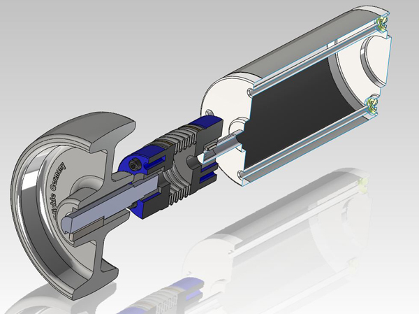
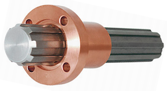
Splines.
-
Forces acting on a Sunk Key.
-
Strength of a Sunk Key.
-
Effect of Keyways : A little consideration will show that the keyway cut into the shaft reduces the load carrying capacity of the shaft. This is due to the stress concentration near the corners of the keyway and reduction in the cross-sectional area of the shaft. It other words, the torsional strength of the shaft is reduced. The following relation for the weakening effect of the keyway is based on the experimental results by H.F. Moore. e = 1 – 0.2 (w/d) – 1.1 (h/d) where e = Shaft strength factor. It is the ratio of the strength of the shaft with
keyway to the strength of the same shaft without keyway,
w = Width of keyway,
d = Diameter of shaft, and
h = Depth of keyway = Thickness of key (t)/2 It is usually assumed that the strength of the keyed shaft is 75% of the solid shaft, which is somewhat higher than the value obtained by the above relation.
In case the keyway is too long and the key is of sliding type, then the angle of twist is increased in the ratio kθ as given by the following relation : kθ = 1 + 0.4 (w/d) + 0.7 (h/d) where kθ = Reduction factor for angular twist. -
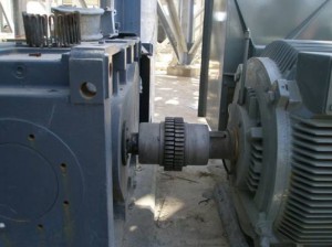
Shaft Couplings.
-
Requirements of a Good Shaft Coupling : A good shaft coupling should have the following requirements :
1. It should be easy to connect or disconnect.
2. It should transmit the full power from one shaft to the other shaft without losses.
3. It should hold the shafts in perfect alignment.
4. It should reduce the transmission of shock loads from one shaft to another shaft.
5. It should have no projecting parts. -
Types of Shaft Couplings.
-
Sleeve or Muff Coupling.
-
Clamp or Compression Coupling.
-
Flange Coupling.
-
Design of Flange Coupling.
-
Flexible Coupling.
-
Bushed Pin Flexible Coupling.
-
Oldham Coupling.
-
Universal Coupling.
Reference A Textbook of Machine Design by R.S. Khurmi and J.K. Gupta


Post Comment
You must be logged in to post a comment.