

[visitor]
This Simple post will give you basics steps to interface LED with 8051 Microcontroller.
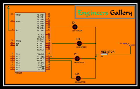
Figure 1 shows how to interface the LEDs to microcontroller. As you can see the Anodes of LEDs are connected through a resistor to Vcc (5V) & the Cathode is connected to the Microcontroller Port 3 (P3.0, P3.1, P3.2, P3.3). So when the Port Pins are HIGH the LEDs are OFF & when the Port Pins are LOW the LEDs are turned ON.
| Basic Flashing LED ALGORITHM |
|
| We now want to flash a LEDs. It works by turning ON a LEDs & then turning it OFFs & then looping back to START. However the operating speed of microcontroller is very high so the flashing frequency will also be very fast to be detected by human eye. |
| Modified Flashing LED ALGORITHM |
|
| You can see in the modified algorithm that after turning ON the LEDs the controller waits for the delay period & then turns OFF the led & again waits for the delay period & then goes back to the start. Here I turn On LEDs sequential. |
Subscribe to view Code
[/visitor]
[member]This Simple post will give you basics steps to interface LED with 8051 Microcontroller.
Figure 1 shows how to interface the LEDs to microcontroller. As you can see the Anodes of LEDs are connected through a resistor to Vcc (5V) & the Cathode is connected to the Microcontroller Port 3 (P3.0, P3.1, P3.2, P3.3). So when the Port Pins are HIGH the LEDs are OFF & when the Port Pins are LOW the LEDs are turned ON.
| Basic Flashing LED ALGORITHM |
|
| We now want to flash a LEDs. It works by turning ON a LEDs & then turning it OFFs & then looping back to START. However the operating speed of microcontroller is very high so the flashing frequency will also be very fast to be detected by human eye. |
| Modified Flashing LED ALGORITHM |
|
| You can see in the modified algorithm that after turning ON the LEDs the controller waits for the delay period & then turns OFF the led & again waits for the delay period & then goes back to the start. Here I turn On LEDs sequential. |
[message_box title=”MESSAGE TITLE” color=”red”]
org 0000h
Enggallery:
mov p3,#0feh
acall delay
mov p3,#0fdh
acall delay
mov p3,#0fbh
acall delay
mov p3,#0f7h
acall delay
jmp Enggallery
delay:
mov r3,#05h
x3: mov r0,#0ffh
x2: mov r1,#0ffh
x1: djnz r1,x1
djnz r0,x2
djnz r3,x3
ret
end
[/message_box]
Here we use delay loop which indicate Microcontroller (8051) to wait for some time.
Here I Post video of this simple project. If you have any doubt than comment it below box. I will help you for sure.
[/member]


