

AC Circuit Theory
The AC Waveform
Direct Current or D.C. as it is more commonly called, is a form of current or voltage that flows around an electrical circuit in one direction only, making it a “Uni-directional” supply. Generally, both DC currents and voltages are produced by power supplies, batteries, dynamos and solar cells to name a few. A DC voltage or current has a fixed magnitude (amplitude) and a definite direction associated with it. For example, +12V represents 12 volts in the positive direction, or -5V represents 5 volts in the negative direction.
We also know that DC power supplies do not change their value with regards to time, they are a constant value flowing in a continuous steady state direction. In other words, DC maintains the same value for all times and a constant uni-directional DC supply never changes or becomes negative unless its connections are physically reversed. An example of a simple DC or direct current circuit is shown below.
DC Circuit and Waveform
An alternating function or AC Waveform on the other hand is defined as one that varies in both magnitude and direction in more or less an even manner with respect to time making it a “Bi-directional” waveform. An AC function can represent either a power source or a signal source with the shape of an AC waveform generally following that of a mathematical sinusoid as defined by:- A(t) = Amax x sin(2πƒt).
The term AC or to give it its full description of Alternating Current, generally refers to a time-varying waveform with the most common of all being called a Sinusoid better known as a Sinusoidal Waveform. Sinusoidal waveforms are more generally called by their short description as Sine Waves. Sine waves are by far one of the most important types of AC waveform used in electrical engineering.
The shape obtained by plotting the instantaneous ordinate values of either voltage or current against time is called an AC Waveform. An AC waveform is constantly changing its polarity every half cycle alternating between a positive maximum value and a negative maximum value respectively with regards to time with a common example of this being the domestic mains voltage supply we use in our homes.
This means then that the AC Waveform is a “time-dependent signal” with the most common type of time-dependant signal being that of the Periodic Waveform. The periodic or AC waveform is the resulting product of a rotating electrical generator. Generally, the shape of any periodic waveform can be generated using a fundamental frequency and superimposing it with harmonic signals of varying frequencies and amplitudes but that’s for another tutorial.
Alternating voltages and currents can not be stored in batteries or cells like direct current (DC) can, it is much easier and cheaper to generate these quantities using alternators or waveform generators when they are needed. The type and shape of an AC waveform depends upon the generator or device producing them, but all AC waveforms consist of a zero voltage line that divides the waveform into two symmetrical halves. The main characteristics of an AC Waveform are defined as:
AC Waveform Characteristics
- The Period, (T) is the length of time in seconds that the waveform takes to repeat itself from start to finish. This can also be called the Periodic Time of the waveform for sine waves, or the Pulse Width for square waves.
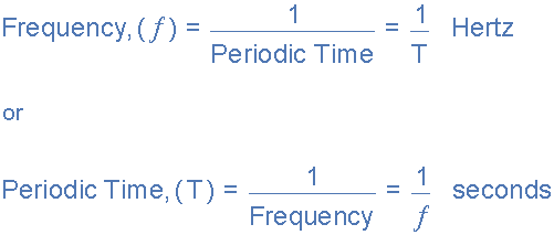
- The Frequency, (ƒ) is the number of times the waveform repeats itself within a one second time period. Frequency is the reciprocal of the time period, ( ƒ = 1/T ) with the unit of frequency being the Hertz, (Hz).
- The Amplitude (A) is the magnitude or intensity of the signal waveform measured in volts or amps.
In our tutorial about Waveforms ,we looked at different types of waveforms and said that “Waveforms are basically a visual representation of the variation of a voltage or current plotted to a base of time”. Generally, for AC waveforms this horizontal base line represents a zero condition of either voltage or current. Any part of an AC type waveform which lies above the horizontal zero axis represents a voltage or current flowing in one direction.
Likewise, any part of the waveform which lies below the horizontal zero axis represents a voltage or current flowing in the opposite direction to the first. Generally for sinusoidal AC waveforms the shape of the waveform above the zero axis is the same as the shape below it. However, for most non-power AC signals including audio waveforms this is not always the case.
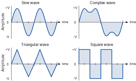
The most common periodic signal waveforms that are used in Electrical and Electronic Engineering are the Sinusoidal Waveforms. However, an alternating AC waveform may not always take the shape of a smooth shape based around the trigonometric sine or cosine function. AC waveforms can also take the shape of either Complex Waves, Square Waves or Triangular Waves and these are shown below.
Types of Periodic Waveform
The time taken for an AC Waveform to complete one full pattern from its positive half to its negative half and back to its zero baseline again is called a Cycle and one complete cycle contains both a positive half-cycle and a negative half-cycle. The time taken by the waveform to complete one full cycle is called the Periodic Time of the waveform, and is given the symbol “T”.
The number of complete cycles that are produced within one second (cycles/second) is called the Frequency, symbol ƒ of the alternating waveform. Frequency is measured in Hertz, ( Hz ) named after the German physicist Heinrich Hertz.
Then we can see that a relationship exists between cycles (oscillations), periodic time and frequency (cycles per second), so if there are ƒ number of cycles in one second, each individual cycle must take 1/ƒ seconds to complete.
Relationship Between Frequency and Periodic Time
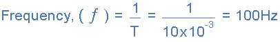
AC Waveform Example No1
1. What will be the periodic time of a 50Hz waveform and 2. what is the frequency of an AC waveform that has a periodic time of 10mS.
1)
 2)
2)
Frequency used to be expressed in “cycles per second” abbreviated to “cps”, but today it is more commonly specified in units called “Hertz”. For a domestic mains supply the frequency will be either 50Hz or 60Hz depending upon the country and is fixed by the speed of rotation of the generator. But one hertz is a very small unit so prefixes are used that denote the order of magnitude of the waveform at higher frequencies such as kHz, MHz and even GHz.
Definition of Frequency Prefixes
| Prefix | Definition | Written as | Periodic Time |
| Kilo | Thousand | kHz | 1ms |
| Mega | Million | MHz | 1us |
| Giga | Billion | GHz | 1ns |
| Terra | Trillion | THz | 1ps |
Amplitude of an AC Waveform
As well as knowing either the periodic time or the frequency of the alternating quantity, another important parameter of the AC waveform is Amplitude, better known as its Maximum or Peak value represented by the terms, Vmax for voltage or Imax for current.
The peak value is the greatest value of either voltage or current that the waveform reaches during each half cycle measured from the zero baseline. Unlike a DC voltage or current which has a steady state that can be measured or calculated using Ohm’s Law, an alternating quantity is constantly changing its value over time.
For pure sinusoidal waveforms this peak value will always be the same for both half cycles ( +Vm = -Vm ) but for non-sinusoidal or complex waveforms the maximum peak value can be very different for each half cycle. Sometimes, alternating waveforms are given a peak-to-peak, Vp-p value and this is simply the distance or the sum in voltage between the maximum peak value, +Vmax and the minimum peak value, -Vmax during one complete cycle.
The Average Value of an AC Waveform
The average or mean value of a continuous DC voltage will always be equal to its maximum peak value as a DC voltage is constant. This average value will only change if the duty cycle of the DC voltage changes. In a pure sine wave if the average value is calculated over the full cycle, the average value would be equal to zero as the positive and negative halves will cancel each other out. So the average or mean value of an AC waveform is calculated or measured over a half cycle only and this is shown below.
Average Value of a Non-sinusoidal Waveform
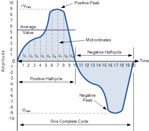
To find the average value of the waveform we need to calculate the area underneath the waveform using the mid-ordinate rule, trapezoidal rule or the Simpson’s rule found commonly in mathematics. The approximate area under any irregular waveform can easily be found by simply using the mid-ordinate rule.
The zero axis base line is divided up into any number of equal parts and in our simple example above this value was nine, ( V1 to V9 ). The more ordinate lines that are drawn the more accurate will be the final average or mean value. The average value will be the addition of all the instantaneous values added together and then divided by the total number. This is given as.
Average Value of an AC Waveform
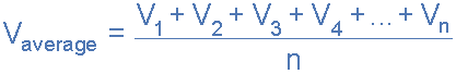 Where: n equals the actual number of mid-ordinates used.
For a pure sinusoidal waveform this average or mean value will always be equal to 0.637 x Vmax and this relationship also holds true for average values of current.
The RMS Value of an AC Waveform
The average value of an AC waveform is NOT the same value as that for a DC waveforms average value. This is because the AC waveform is constantly changing with time and the heating effect given by the formula ( P = I 2.R ), will also be changing producing a positive power consumption. The equivalent average value for an alternating current system that provides the same power to the load as a DC equivalent circuit is called the “effective value”.
This effective power in an alternating current system is therefore equal to: ( I 2.R.Average ). As power is proportional to current squared, the effective current, I will be equal to √ I squared Ave. Therefore, the effective current in an AC system is called the Root Mean Squared or R.M.S. value and RMS values are the DC equivalent values that provide the same power to the load.
The effective or RMS value of an alternating current is measured in terms of the direct current value that produces the same heating effect in the same value resistance. The RMS value for any AC waveform can be found from the following modified average value formula.
RMS Value of an AC Waveform
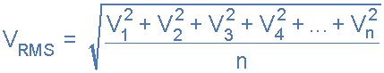
Where: n equals the number of mid-ordinates.
For a pure sinusoidal waveform this effective or R.M.S. value will always be equal to 1/√2 x Vmax which is equal to 0.707 x Vmax and this relationship holds true for RMS values of current. The RMS value for a sinusoidal waveform is always greater than the average value except for a rectangular waveform. In this case the heating effect remains constant so the average and the RMS values will be the same.
One final comment about R.M.S. values. Most multimeters, either digital or analogue unless otherwise stated only measure the R.M.S. values of voltage and current and not the average. Therefore when using a multimeter on a direct current system the reading will be equal to I = V/R and for an alternating current system the reading will be equal to Irms = Vrms/R.
Also, except for average power calculations, when calculating RMS or peak voltages, only use VRMS to find IRMS values, or peak voltage, Vp to find peak current, Ip values. Do not mix the two together average, RMS or peak values as they are completely different and your results will be incorrect.
Form Factor and Crest Factor
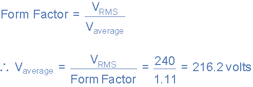
Although little used these days, both Form Factor and Crest Factor can be used to give information about the actual shape of the AC waveform. Form Factor is the ratio between the average value and the RMS value and is given as.
 For a pure sinusoidal waveform the Form Factor will always be equal to 1.11. Crest Factor is the ratio between the R.M.S. value and the Peak value of the waveform and is given as.

For a pure sinusoidal waveform the Crest Factor will always be equal to 1.414.
AC Waveform Example No2
A sinusoidal alternating current of 6 amps is flowing through a resistance of 40Ω. Calculate the average voltage and the peak voltage of the supply.
The R.M.S. Voltage value is calculated as:
![]() The Average Voltage value is calculated as:
The Average Voltage value is calculated as:
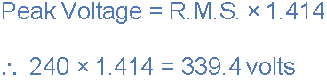
 The Peak Voltage value is calculated as:
 The use and calculation of Average, R.M.S, Form factor and Crest Factor can also be use with any type of periodic waveform including Triangular, Square, Sawtoothed or any other irregular or complex voltage/current waveform shape. Conversion between the various sinusoidal values can sometimes be confusing so the following table gives a convenient way of converting one sine wave value to another.
Sinusoidal Waveform Conversion Table
| Convert From | Multipy By | Or By | To Get Value |
| Peak | 2 | (√2)2 | Peak-to-Peak |
| Peak-to-Peak | 0.5 | 1/2 | Peak |
| Peak | 0.7071 | 1/(√2) | RMS |
| Peak | 0.637 | 2/π | Average |
| Average | 1.570 | π/2 | Peak |
| Average | 1.111 | π/(2√2) | RMS |
| RMS | 1.414 | √2 | Peak |
| RMS | 0.901 | (2√2)/π | Average |
In the next tutorial about Sinusoidal Waveforms we will look at the principal of generating a sinusoidal AC waveform (a sinusoid) along with its angular velocity representation.


