

INTRODUCTION:
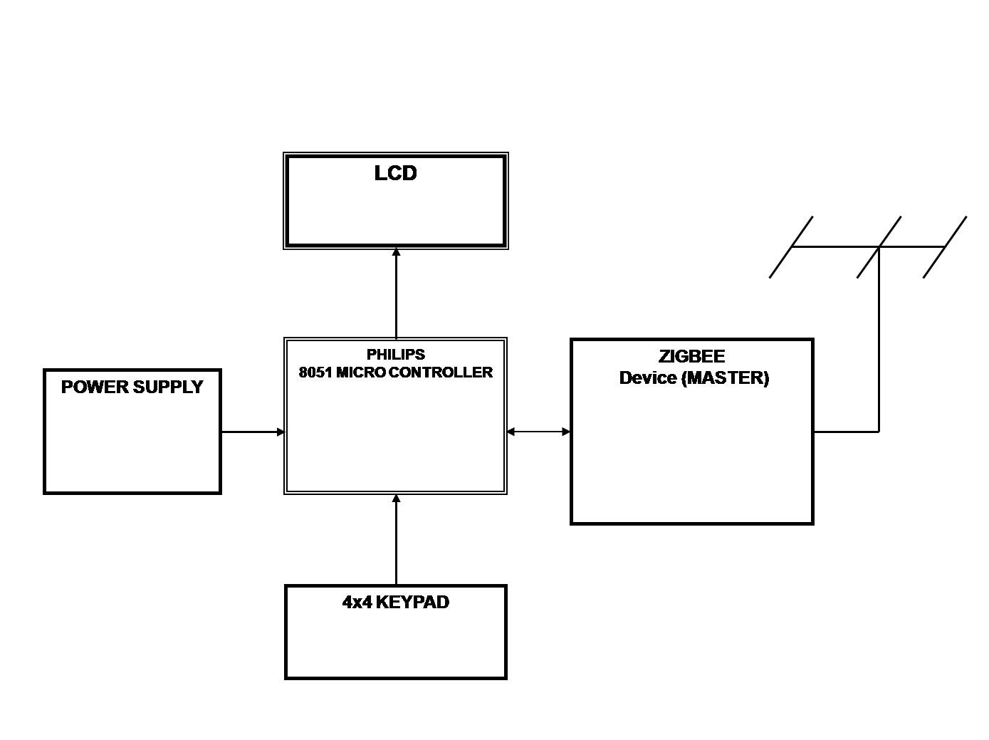
The aim of the project is Zigbee communication between two embedded applications i.e. to interface a 4×4 Keyboard with 8051 Microcontroller. By press any key those key data read by the micro-controller and its display on the LCD and send to the Zigbee transmitter. This Zigbee transmitter will act as Master. This Master sends data to the Zigbee receiver. Zigbee receiver will act as a Receiver. This receiver sends the received data to the 8051 micro-controller and depending on the data the receiver micro-controller controls the appropriate device.
Zigbee device can play a role as a master or slave. Master tries to connect itself to other devices and slave is waiting to be connected from other devices. A Zigbee connection can always be made from pair of master and slave devices.
BLOCK DIAGRAM:
ZIGBEE REMOTE:
RECEIVER SECTION:
Micro-controller:
The 8051 is a low cost Micro controller. It has a 40-pin DIP configuration and other components are interfaced to its ports. The entire functionality of the Keyboard and LCD device is under the control of Micro controller. The Micro controller takes input from the external sources and routes them to the appropriate devices as programmed in it.
8051 based microcontrollers typically include one or two UARTs, two or three timers, 128 or 256 bytes of internal data RAM (16 bytes of which are bit-addressable), up to 128 bytes of I/O, 512 bytes to 64kB of internal program memory, and sometimes a quantity of extended data RAM (ERAM) located in the external data space. The original 8051 core ran at 12 clock cycles per machine cycle, with most instructions executing in one or two machine cycles. With a 12 MHz clock frequency, the 8051 could thus execute 1 million one-cycle instructions per second or 500,000 two-cycle instructions per second. Enhanced 8051 cores are now commonly used which run at six, four, two, or even one clock per machine cycle, and have clock frequencies of up to 100 MHz, and are thus capable of an even greater number of instructions per second.
LCD display unit:
The 4×20 LCD (backlit) provides a very functional, low-cost LCD that can be easily controlled. The LCD display consists of four lines by 20 characters and provides basic text wrapping so that your text looks right on the display. In addition, the LCD also provides you with full control over all of its advanced LCD features, allowing you to move the cursor anywhere on the display with a single instruction and turn the display on and off in any configuration. It supports the same visible characters as the ASCII values.
Zigbee Communication:
The XBee OEM RF Modules were engineered to operate within the ZigBee protocol and support the unique needs of low-cost, low-power wireless sensor net-works. The modules require minimal power and provide reliable delivery of data between remote devices. Both modules operate within the ISM 2.4 GHz frequency band and are pin-for-pin compatible with each other.
Keypad:
Keyboard allows interacting with application by typing desired command and Messages.
4×4 Matrix keys are connected to microcontroller .Each and every key is designed for a particular function.
Power Supply Unit:
Power supply unit is used to provide a constant 5Volts, 1.5Amp supply to different ICs. This is a standard circuit using external 12V DC adopter and fixed 3-pin voltage regulator. Diode is added in series to avoid Reverse voltage Protection.


