What is a Potentiometer?
Potentiometer is a small sized electronic component whose resistance can be adjusted manually. Increasing or decreasing the value of resistance controls the amount of current flowing in a circuit. The potentiometer is used in various electronics, for example: is used as volume knob in music systems, as fan regulators etc. Potentiometer has two strips made on it resistive and conductive. Resistive strip is made of carbon and is responsible for potentiometer’s resistance variance feature. Conductive strip helps the potentiometer to carry the current into the circuit in accordance with the resistance. To understand the theory of our humble potentiometers (or pots), let us know the parts of the potentiometer:
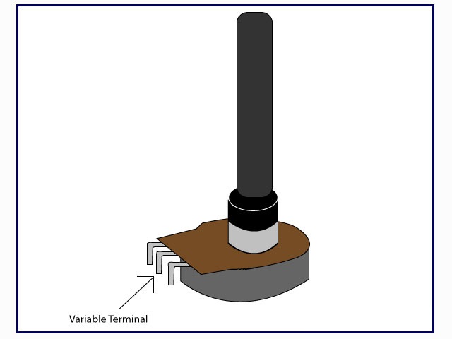
- Lugs: Potentiometers by convention have three lugs. They are numbered 1, 2, and 3 as shown in the figure.
- Shaft: This is a plastic/metallic stick which is used to turn the potentiometer.
- Resistive Strip: This is the heart of the potentiometer. It is a carbon strip that is printed on a phenolic strip. There are metal contacts in the end to connect it to the lugs.
- Metal Wiper: When we rotate the shaft, it in turn rotates a metallic wiper which connects the lug 1 and lug2.
Circuit Symbol
Working of Potentiometers
The metallic wiper acts as a conducting path between the lug 1 and lug 2. So the resistance between the left lug and the centre lug is the resistance of the part of carbon strip over which the metallic wiper has traversed. When we rotate the shaft of the potentiometer, we actually rotate the metallic wiper attached to it and hence change the resistance. This way the pot acts as a variable resistance.
Taper
The relation between the position of wiper and the resistance is called the taper of the potentiometer. In other words taper decides how the resistance will vary when we turn the pot. Taper divides potentiometers broadly into two types:
- Linear Pots: In these pots, the resistance between lug 1 and lug 2 is directly proportional to the distance moved by the wiper. These are the common pots found in labs and are inexpensive.
- Logarithmic Pots: In these pots, the resistance between lug1 and lug 2 is a logarithmic function of the wiper position. Actually their taper graph looks more like a 10x graph. They are expensive and not readily available. Also there are reverse logarithmic pots which are similar to logarithmic pots, which have a taper opposite to that of log pots. More about logarithmic pots in the next section.
How to check the taper with an ohm meter? Set the pot to the centre position (50% rotation) and measure the resistance between the centre pin and each of the outer pins. If the resistance is equal (50% of the pots value) the pot is linear. If the values are not equal, the pot is an log taper.
Logarithmic Pots
These pots are extensively used in audio electronics and hence are also called audio pots. The reason for their wide use in audio electronics especially in volume control owes to the perception of loudness by human ears. If two sources produce sound, then the human ear will perceive one source twice as loud as the other only if the intensity of sound of one source is ten times the other. So by using audio pots we are able to achieve perceivable change in loudness by slight turning of the pot. If a linear pot is used instead, we will notice that loudness changes only when the pot is turned to its full extent.
How logarithmic tapering is achieved? Well to answer this, we need to go back to the heart of the potentiometer, the resistive strip. One way to achieve log taper is to change the width of the cross section of the resistive strip. For cheaper log pots, the cross section width remains same but two or three resistive materials of different resistivity are used to approximate a log taper.
How to make a linear pot behave like a logarithmic pot? Log pots are expensive and tough to find. One idea is to make a circuit whose transfer function is not exactly but similar to logarithmic function. One such circuit is as follows:
Let the total resistance of the pot be R, R1 be the resistance between lug 3 and lug 1 and R2 be the resistance between lug 1 and lug 2. R3 is a resistance put in parallel to R2. We define x=R2/R (the fraction of resitance swept by the wiper) and y=R3/R.
The relation between input voltage Vin and output voltage across R3 come out to be
Below is the graph of Vin/Vout when y=4 and x is varied between 0 to 1 which looks similar to a log graph (isn’t it?)
The only catch here is that using the above circuit in place of a log pot will reduce the input resistance that the source voltage will see. So some amount of experimentation should be done to choose the value of y. Similarly, reverse log pots can be emulated using linear pot by simply putting R3 resistance across R1 and taking the output voltage across R2.
Ways to Connect Pot
- Trimmer resistance: Connecting pot as shown in the figure way makes it behave like a variable resistance. When you turn the shaft you are basically reducing the resistance.
It is advisable to short lug 1 and lug 2 because if the wiper shorts then there is resistance which will prevent the full signal to pass to Vout.
- Voltage Divider: This is generally used to control the amount of input signal passing to the output.
TRIMMING POTENTIOMETERS
These are also potentiometers but are “set and forget” devices which are directly mounted on to PCB or bread board to fine tune the circuit. For example, you want to bias a transistor to an exact potential which in turn relies on resistance, you can use a trim pot to get the exact voltage (by changing the resistance) and then forget about it. One might have to use a screwdriver to change the resistance which might not be very convenient but this way it is difficult to change the resistance once you have set it to the desired resistance.

