

The power from one pulley to another may be transmitted by any of the following types of flat belt drives.
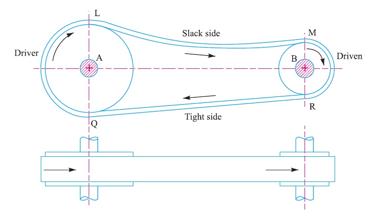
1. Open belt drive. The open belt drive, as shown in Fig. 2, is used with shafts arranged parallel and rotating in the same direction. In this case, the driver A pulls the belt from one side (i.e. lower side RQ) and delivers it to the other side (i.e. upper side LM). Thus the tension in the lower side belt will be more than that in the upper side belt. The lower side belt (because of more tension) is known as tight side whereas the upper side belt (because of less tension) is known as slack side, as shown in Fig. 2.
2. Crossed or twist belt drive. The crossed or twist belt drive, as shown in Fig. 3, is used with shafts arranged parallel and rotating in the opposite directions. In this case, the driver pulls the belt from one side (i.e. RQ) and delivers it to the other side (i.e. LM). Thus, the tension in the belt RQ will be more than that in the belt LM. The belt RQ (because of more tension) is known as tight side, whereas the belt LM (because of less tension) is known as slack side, as shown in Fig. 3.
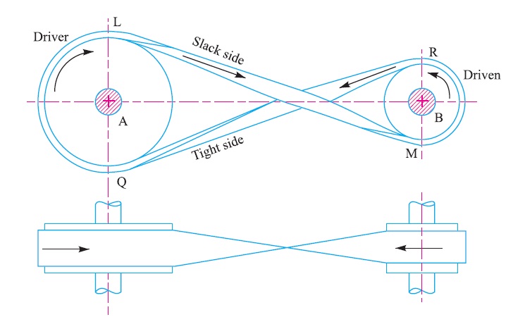
A little consideration will show that at a point where the belt crosses, it rubs against each other and there will be excessive wear and tear. In order to avoid this, the shafts should be placed at a maximum distance of 20 b, where b is the width of belt and the speed of the belt should be less than 15 m/s.
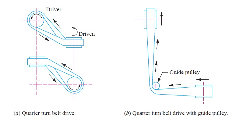
3. Quarter turn belt drive. The quarter turn belt drive (also known as right angle belt drive) as shown in Fig. 4 (a), is used with shafts arranged at right angles and rotating in one definite direction. In order to prevent the belt from leaving the pulley, the width of the face of the pulley should be greater or equal to 1.4 b, where b is width of belt.
In case the pulleys cannot be arranged as shown in Fig. 4 (a) or when the reversible motion is desired, then a quarter turn belt drive with a guide pulley, as shown in Fig. 4 (b), may be used.
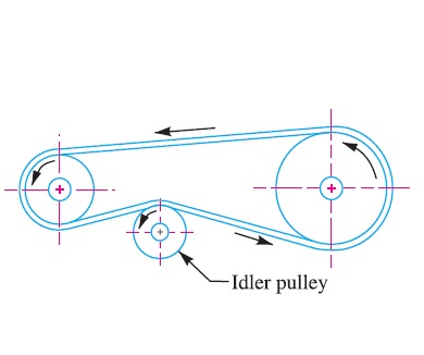
4. Belt drive with idler pulleys. A belt drive with an idler pulley (also known as jockey pulley drive) as shown in Fig. 5, is used with shafts arranged parallel and when an open belt drive can not be used due to small angle of contact on the smaller pulley. This type of drive is provided to obtain high velocity ratio and when the required belt tension can not be obtained by other means.
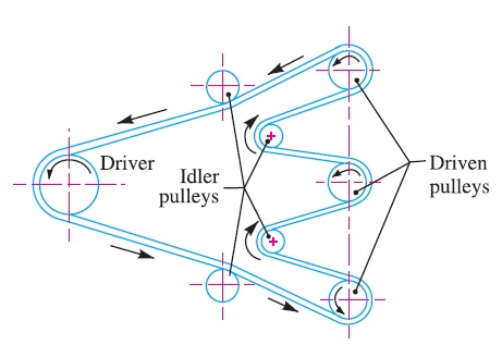
When it is desired to transmit motion from one shaft to several shafts, all arranged in parallel, a belt drive with many idler pulleys, as shown in Fig. 18.8, may be employed.
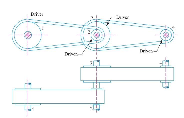
5. Compound belt drive. A compound belt drive as shown in Fig. 7, is used when power is transmitted from one shaft to another through a number of pulleys.
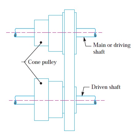
6. Stepped or cone pulley drive. A stepped or cone pulley drive, as shown in Fig. 8, is used for changing the speed of the driven shaft while the main or driving shaft runs at constant speed. This is accomplished by shifting the belt from one part of the steps to the other.
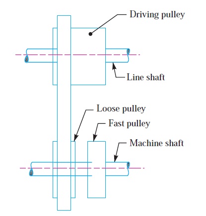
7. Fast and loose pulley drive. A fast and loose pulley drive, as shown in Fig. 9, is used when the driven or machine shaft is to be started or stopped whenever desired without interfering with the driving shaft. A pulley which is keyed to the machine shaft is called fast pulley and runs at the same speed as that of machine shaft. A loose pulley runs freely over the machine shaft and is incapable of transmitting any power. When the driven shaft is required to be stopped, the belt is pushed on to the loose pulley by means of sliding bar having belt forks.
Reference A Textbook of Machine Design by R.S.Khurmi and J.K.Gupta


