

Threading and Timers in Atmega328p
[nextpage title=”Summary” ][/nextpage]My motivation for this project was to minimize the usage of functions such as _delay_ms(), _delay_us() and their derivatives with some exceptions, like delays to control the LCD.
Delay pauses the whole program, so if one is using delay for 10 seconds everything will pause for those 10 seconds, therefore nothing can be done in those 10 seconds.
Although if we use interrupt, there is a separate hardware known as timer which counts the clock ticks and generate interrupt, after specified number of clock ticks have been counted.
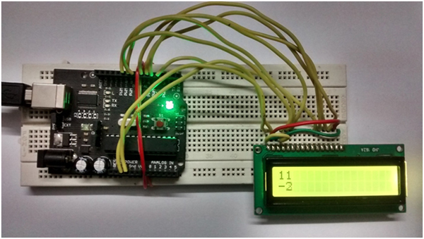
In this project I’m using LCD JHD162A. It has 2 rows and 16 columns.
I build a task scheduler which switches between two threads in an interval of 5.5 seconds.
First task(thread 1) is to increment an integer value displayed on first row of LCD every second.
Second task(thread 2) is decrement an integer value displayed on second row every two seconds.
Both integers start from Zero.
Example:
1) t1 is running and increments the integer in the first row every second
2) After 5.5 seconds, t1 stops and t2 starts decrementing the integer in the second row every 2 seconds
3) After 5.5 seconds, stop t2, start t1, go back to 1)

A thread is a lightweight process that is executed independently. But due to hardware limitation let’s assume that a thread is simply a function manipulating one of the integers mentioned above. Since Atmega328P is equipped with only one ALU, either thread1 or thread2 is able to run. They can never run at the same time.
How I am uploading code into arduino:
f = <source_code’s_file_name>
avr-gcc -g -mmcu=atmega328p -Wall -Os $(f).c -o $(f).elf
avr-objcopy -j .text -j .data -O ihex $(f).elf $(f).hex
sudo avrdude -F -V -c arduino -p m328 -P /dev/ttyUSB* -b 57600 -e -U flash:w:$(f).hex
Just type these four commands, in the same order, in your terminal and remember to put the source code’s filename in variable “f”. These command are for Linux users only.
First command stores the filename in variable “f”, second command is used to convert source code to .elf file, third command is used to convert that .elf file to .hex file which can be uploaded on atmega328p, fourth command is used to upload that .hex file.
Intro to Atmega328p and it’s timers:
Atmega328p is equipped ,viz. timer0, timer1, timer2; two are 8-bits and one is 16-bit. Maximum number of clock ticks that a timer can count depends on the size of the register.
Timer 0 and timer 2 use two different 8-bit register, whereas, timer 1 is use a 16-bit register.
An 8-bit register can count upto 2^8 = 256(0 to 255) similarly 16-bit register can count up 2^16 = 65536(0 to 65535). With the available resources I can generate an interrupt at every (65536/clock freq) 65536/1,60,00,000 = 4.0959375ms.
To increase this maximum time, every timer is given a set of pre-scalars, which are in power of 2’s. A prescaler divides the clock freq by that number. In 16-bit timer maximum pre-scalar available is 1024, therefore now I can generate an interrupt
(65536/(clk freq/1024)) 65536*1024/1,60,00,000 = 4.19424 sec
Same goes for 8-bit timer.
[/nextpage][nextpage title=”Description” ]
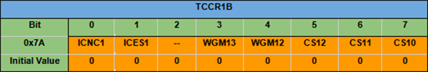
Bit 7 – ICNC1: Input Capture Noise Canceler
Setting this bit (to one) activates the Input Capture Noise Canceler. When the noise canceler is activated, the input from the Input Capture pin (ICP1) is filtered.
• Bit 6 – ICES1: Input Capture Edge Select
This bit selects which edge on the Input Capture pin (ICP1) that is used to trigger a capture event.
• Bit 5 – Reserved Bit
This bit is reserved for future use. For ensuring compatibility with future devices, this bit must be written to zero when TCCR1B is written.
• Bit 4:3 – WGM13:2: Waveform Generation Mode
See TCCR1A Register description.
• Bit 2:0 – CS12:0: Clock Select
The three Clock Select bits select the clock source to be used by the Timer/Counter
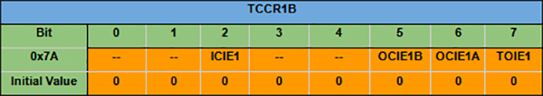
• Bit 7, 6 – Res: Reserved Bits
These bits are unused bits in the ATmega48PA/88PA/168PA/328P, and will always read as zero.
• Bit 5 – ICIE1: Timer/Counter1, Input Capture Interrupt Enable
When this bit is written to one, and the I-flag in the Status Register is set (interrupts globally enabled), the Timer/Counter1 Input Capture interrupt is enabled.
• Bit 4, 3 – Res: Reserved Bits
These bits are unused bits in the ATmega48PA/88PA/168PA/328P, and will always read as zero.
• Bit 2 – OCIE1B: Timer/Counter1, Output Compare B Match Interrupt Enable
When this bit is written to one, and the I-flag in the Status Register is set (interrupts globally enabled), the Timer/Counter1 Output Compare B Match interrupt is enabled. The corresponding Interrupt Vector is executed when the OCF1B Flag, located in
TIFR1, is set.
• Bit 1 – OCIE1A: Timer/Counter1, Output Compare A Match Interrupt Enable
When this bit is written to one, and the I-flag in the Status Register is set (interrupts globally enabled), the Timer/Counter1 Output Compare A Match interrupt is enabled. The corresponding Interrupt Vector is executed when the OCF1A Flag, located in TIFR1, is set.
• Bit 0 – TOIE1: Timer/Counter1, Overflow Interrupt Enable
When this bit is written to one, and the I-flag in the Status Register is set (interrupts globally enabled), the Timer/Counter1 Overflow interrupt is enabled.
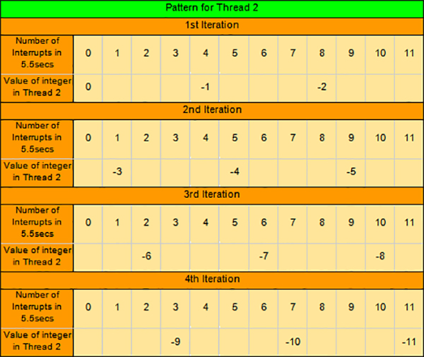
My task is to simulate threading. I designed two task one in which a counter increments after every second and another in which counter decrements after every two seconds.
Both the tasks are switched every 5.5 seconds and previous state of the task is preserved.
● timers relation
In this project I’m using timer1, which is a 16 bit timer therefore maximum count it can go for is 2^16 = 65536.
Minimum value of time that I want is 0.5 seconds.
My Arduino is equipped with a frequency oscillator, having freq. 1,60,00,000Hz.
Therefore to generate an interrupt at every 0.5 seconds
Count = (0.5 * 1,60,00,000)/1 – 1 = 79,99,999
I need a register capable of counting 79,99,999(which is not available).
So I decided to use a pre-scalar with a value of 256. Now for every to generate an interrupt at every 0.5 seconds
Count = (0.5 * 1,60,00,000)/256 – 1 = 31249
I need a register capable of counting 31249(16 bit timer with a prescaler of 256 can easily do that).
Therefore, after every 0.5 seconds an interrupt is generated
● logic
Both thread follows a pattern which can be simulated by generating an interrupt of 0.5 seconds.
Therefore if a variable is initialised to keep track on the pattern for a specific thread, it can be reseted to zero after every complete cycle of that specific thread.
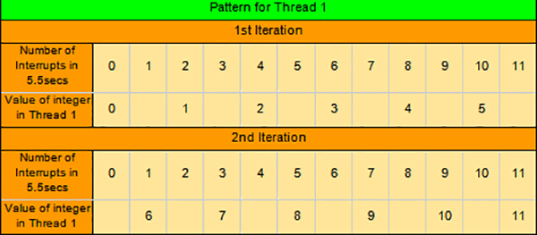
And thread 2 repeats its pattern after four iterations.
Description of Source Code:
I used my own library lcd.h to display integer value of thread 1 and thread 2 on 16×2 LCD.
First I initialised timer() function and defined relevant variables globally, then in main() function I declared pin 4,5,6,7,8,9 as output and I initialized lcd via start() allowed global interrupt via sei() and initialised timer via timer().
After initializing and defining necessary things I displayed 0 on both rows of lcd, and started an infinite loop.
Algorithm that I’m using is in ISR() block, which is executed on every 0.5 second interrupt.
For more details please refer source code, it has been explained with comments in it.
[/nextpage][nextpage title=”Circuit Diagram” ]
[/nextpage]


