

Stresses in Flywheel Arms
The following stresses are induced in the arms of a flywheel.
1. Tensile stress due to centrifugal force acting on the rim.
2. Bending stress due to the torque transmitted from the rim to the shaft or from the shaft to the rim.
3. Shrinkage stresses due to unequal rate of cooling of casting. These stresses are difficult to determine.
We shall now discuss the first two types of stresses as follows:
1. Tensile stress due to the centrifugal force
Due to the centrifugal force acting on the rim, the arms will be subjected to direct tensile stress whose magnitude is same as discussed in the previous article.
∴ Tensile stress in the arms,
σt1 = 3/4 σt = 3/4 ρ v^2
2. Bending stress due to the torque transmitted
Due to the torque transmitted from the rim to the shaft or from the shaft to the rim, the arms will be subjected to bending, because they are required to carry the full torque load. In order to find out the maximum bending moment on the arms, it may be assumed as a centilever beam fixed at the hub and carrying a concentrated load at the free end of the rim as shown in Fig. 1.
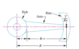
Let T = Maximum torque transmitted by the shaft,
R = Mean radius of the rim,
r = Radius of the hub,
n = Number of arms, and
Z = Section modulus for the cross-section of arms.
We know that the load at the mean radius of the rim,
F = T/R
∴ Load on each arm = T / R n
and maximum bending moment which lies on the arm at the hub,
M = T (R – r) / R n
∴ Bending stress in arms,
σb1 = M / Z = T (R – r)/ R n Z
∴ Total tensile stress in the arms at the hub end,
σ = σt1 + σb1
Notes:
1. The total stress on the arms should not exceed the allowable permissible stress.
2. If the flywheel is used as a belt pulley, then the arms are also subjected to bending due to net belt tension (T1 – T2), where T1 and T2 are the tensions in the tight side and slack side of the belt respectively.
Therefore the bending stress due to the belt tensions,
σb2 = 2 × (T1 – T2) (R – r) / n × Z
… (Q Only half the number of arms are considered to be effective in transmitting the belt tensions)
∴ Total bending stress in the arms at the hub end,
σb = σb1 + σb2
and the total tensile stress in the arms at the hub end,
σ = σt1 + σb1 + σb2
Reference A Textbook of Machine Design by R.S.Khurmi and J.K.Gupta


