

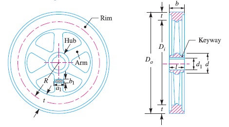
Stresses in a Flywheel Rim : A flywheel, as shown in Fig. 1, consists of a rim at which the major portion of the mass or weight of flywheel is concentrated, a boss or hub for fixing the flywheel on to the shaft and a number of arms for supporting the rim on the hub.
The following types of stresses are induced in the rim of a flywheel:
1. Tensile stress due to centrifugal force,
2. Tensile bending stress caused by the restraint of the arms, and
3. The shrinkage stresses due to unequal rate of cooling of casting. These stresses may be very high but there is no easy method of determining.
This stress is taken care of by a factor of safety.
We shall now discuss the first two types of stresses as follows:
1. Tensile stress due to the centrifugal force
The tensile stress in the rim due to the centrifugal force, assuming that the rim is unstrained by the arms, is determined in a similar way as a thin cylinder subjected to internal pressure.
Let b = Width of rim,
t = Thickness of rim,
A = Cross-sectional area of rim = b × t,
D = Mean diameter of flywheel
R = Mean radius of flywheel,
ρ = Density of flywheel material,
ω = Angular speed of flywheel,
v = Linear velocity of flywheel, and
σt = Tensile or hoop stress.
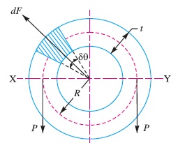
Consider a small element of the rim as shown shaded in Fig. 2. Let it subtends an angle δθ at the centre of the flywheel.
Volume of the small element = A.R.δθ
∴ Mass of the small element,
dm = Volume × Density
= A.R.δθ.ρ = ρ.A.R.δθ
and centrifugal force on the element,
dF = dm.ω^2.R = ρ.A.R.δθ.ω^2.R
= ρ.A.R^2.ω^2.δθ
Vertical component of dF
= dF.sin θ
= ρ.A.R^2.ω^2.δθ sin θ
∴ Total vertical bursting force across the rim diameter X-Y,
= ρ.A R^2.ω^2
0
sin d
∫ π θ θ
= ρ.A.R2.ω2[ ]0 – cos π θ = 2 ρ.A.R^2.ω^2 …(i)
This vertical force is resisted by a force of 2P, such that
2P = 2σt × A …(ii)
From equations (i) and (ii), we have
2ρA.R2.ω2 = 2 σt × A
∴ σt = ρ.R2.ω2 = ρ.v^2 …( Q v = ω.R) …(iii)
when ρ is in kg / m^3 and v is in m / s, then σt will be in N / m2 or Pa.
2. Tensile bending stress caused by restraint of the arms
The tensile bending stress in the rim due to the restraint of the arms is based on the assumption that each portion of the rim between a pair of arms behaves like a beam fixed at both ends and uniformly loaded, as shown in Fig. 3, such that length between fixed ends,
1 = π D/n = 2 π R /n
The uniformly distributed load (w) per metre length will be equal to the centrifugal force between a pair of arms.
∴ w = b.t.ρ.ω2.R N/m
We know that maximum bending moment,
M = w l^2 / 12 = b t ρ w^2 R (2 π R/ n )^2/12
and section modulus,
Z = 1/6 b × t^2
∴ Bending stress,
σb = M/Z = b t ρ w^2 R (2 π R/ n )^2/12 × 6/b t^2
= 19.74 ρ ω^2 R^3 / (n^2 t ) = 19.74 ρ v^2 R / (n^2 t ) …(Substituting ω = v/R) ……(iv)
= 3/4 σt + 1/4 σb = 3/4 ρ.v^2 + 1/4 (19.74 ρ v^2 R/n^2 t) ……(v)


")


")


