

Introduction:
To progress this application on your burn with LEDs oil we button to tell the LED lighting using a button what questions such as the Frequently for teachers that Imagine me being asked is simple that I think would be a good practice for you to completely understand the Arduino’s logic.
First half Let me give you some information about the elements used then step by step I hope :)) Ingredients 1-LED 2-Button 3-2 pieces 220ohm resistor 4-Arduino’s r3 What is Led? Illumination LED ongoing rapid development in the future of the world The word Light Emitting Diode – is composed of Light Emitting Diode’s initials. The LED converts electrical energy to light the semiconductor light element led direction of the circuit connection is important. Led Lamps spend on electricity because they also have a one-way diode. If you tried to take the opposite direction you let the collar.
The lengths of the legs of LED lamps in normal conditions are different from each other. Long leg (+) means the anode and the short leg (-), that is the cathode.
What button?
Electronic buttons, logic 1 or logic 0 data are based on circuit connection status when pressed. Although the structural opening in the circuit is very simple – it is a critical role for the use as closure is not so simple. Push button comprises electric arc continues for a certain time. This arc can cause problems, especially in sensitive electronic circuits. For example, for a period not extinguished arc routine will detect mikrodenetleyi program that detects logic 1 in a second edition.
What is resistance?
The voltage and current applied to the circuit followed until it reaches from one end to the other end face some difficulties on the way. These difficulties affect the passage of electrons or retarding forces. This can be termed resistance to these forces. Our gösterilir.devre briefly with Ohm to divide the current, the resistance applied to the Frequently we want to set the rate.
APPLICATION PROCEDURE
1-Circuit Setup
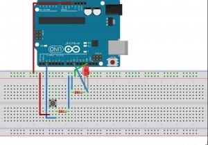
program using the circuit in working condition I tried to draw my view based on more simplistic but button and led resistance to writing as I want to tell you before I can not make a little event mixed. I for LEDs to enter you need to replace the 10.p i the way you want after changing pins in 2 line.
Namely
button on the left leg + u think so 5v hooked
one end of the resistance of the right leg buttons and 2 I connected the .p
hooked one end of the resistance of LEDs in a leg.
LEDs in the other leg 10.p the hooked
hooked idle resistance remaining legs GND to that soil.
You connect as Arduino coming from 5v and the earth in ways no longer …
 Writing code with 2-Arduino

</p><p>int butonPin= 2;<br />int ledPin = 10;</p><p>int butonDurum= 0;</p><p>void setup() {<br />pinMode(ledPin, OUTPUT);<br />pinMode(butonPin, INPUT);<br />}</p><p>void loop(){<br />butonDuruö= digitalRead(butonPin);<br />if(butonDurum== HIGH) {</p><p>digitalWrite(ledPin, HIGH);<br />}<br />else{</p><p>digitalWrite(ledPin, LOW);<br />}<br />}</p><p>Description:
Here the transaction is very simple ago button and LED to pin assignment process yaptık.10 and 2 then we define a variable to control the status of the button.
button is pressed on the control with if logic 1 and LEDs will be made by applying the active led to the command of the pins canceled by pressing the flashing process that will take place in the Lower
Installation
Most beauty where these though gerek.derl process the first application also told I like the program in the upper left (tiger) after compiling the form click on the button performed the installation.


