

Scotch Yoke Mechanism : Understanding
[nextpage title=”Chapter 1″ ]CHAPTER 1
INTRODUCTION
A mechanism is a combination of number of bodies assembled in such a way that the motion of one causes constrained and predictable motion to the other. Mechanisms are used to convert the given motions into useful mechanical motions. Mechanisms transmit or transform motion.
Four bar chain mechanism is a commonly used mechanism. It has got four links forming a kinematic chain. It is used in many machines because of its simplicity compared to other mechanisms. Different configuration for this mechanism can be obtained by fixing different links of the mechanism. This process of fixing the links is known as inversion of a mechanism.
[sam id=”4″ codes=”true”]
This scotch yoke mechanism is used to convert the rotary motion of the crank into sliding motion. As the crank rotates, the horizontal portion of the link slides or reciprocates in the fixed link. Scotch yoke mechanism is obtained when one of the sliding links of a double slider-crank chain is fixed. The advantage of scotch yoke mechanism over the slider crank mechanism is that it has lesser moving parts and smoother operation. This mechanism is most commonly used in control valve actuators in high pressure oil and gas pipelines. Now a day it is also used in various internal combustion engines such as Bourke engine, syTech engine and many hot air engines and steam engines.
From the literature survey the information available regarding the inversion of four bar chain is insufficient. Hence the project is proposed to study and fabrication of scotch yoke mechanism. The following are the main aspects of the project
- To study four bar chain, slider crank and double slider crank.
- To study its inversions
- To fabricate scotch yoke mechanism
- To analyze its motion and discuss its advantages, disadvantages and applications
[/nextpage]
[nextpage title=”Chapter 2″ ]
CHAPTER.2
MECHANISM
A mechanism is a combination of resistant bodies, so interconnected that by applyingforce or motion to one or more of those bodies, some of those bodies are caused to perform desired work accompanied by desired motions. Mechanisms are used to convert one type of motion into another. The connections present in a mechanism are called kinematic pairs. Kinematic pairs can be classified as higher pair or lower pair.
A mechanism is usually a piece of a larger process or mechanical device. Sometimes an entire machine may be referred to as a mechanism. Examples are the steering mechanism in acar, or the winding mechanism of a wristwatch. Multiple mechanisms are machines.
[sam id=”4″ codes=”true”]
Kinematics link or element:
Each part of machine which moves relative to some other part is known as kinematic link or element. A link may have consisted of several parts which are manufactured as separate unit.
Characteristic of link:
It must be a resistance body.
It should have relative motion.
Kinematics pair:
Kinematics pair has two elements or link together which have relative motion between them. The motion between them completely or successfully constrained.
Classification of Kinematics pair:
- On the basis of contact:
Lower pair: A pair of links having surface or area contact between the members is known as a lower pair. The contact surface of the two links is similar.
Example: shaft rotating in a bearing
Higher pair: A pair of links having point or line contact between the links is known as a higher pair. The contact surface of the two links is dissimilar.
Example: wheel rolling on a surface
- On the basis of type of constraint:
Closed pair: In a closed pair, the elements of the pair are held together mechanically.
Example: screwpair
Unclosed pair: An unclosed pair will form when two links of a pair are in contact either due to force of gravity or some spring action.
Example: cam and a follower pair
- On the basis of type of relative motion:
Sliding pair: Two links have sliding motion relative to each other. A rectangular rod in a rectangular hole in a prism forms a sliding pair.
Screw pair: screw pair is formed when two mating links have a turning as well as sliding motion between them.
Turning pair: A turning pair is formed when one link has a turning or revolving motion relative to the other. Circular shaft revolving inside a bearing is a turning pair.
Spherical pair: It is formed when one link in the form of a sphere turns inside a fixed link. The ball and socket joint is a spherical pair.
Rolling pair: It is formed when the links of a pair have a rolling motion relative to each other.
Inversion of mechanism:
When one of the links is fixed in a kinematics chain ,it is called inversion of a mechanism .so we can obtain as many mechanisms as the number of link in a kinematic chain by fixing ,in turn , different link in a kinematics chain . This method of obtaining different mechanism by fixing different links in a kinematic chain is known as inversion.
Types of inversion:
- Four bar chain or quadric cycle chain:
Crank-Rocker mechanism
Double crank mechanism
Double rocker mechanism
- Single slider crank chain:
Bull engine or pendulum engine
Oscillating cylinder engine
Rotary engine
Crank & slotted quick return mechanism
Whitworth quick return mechanism
- Double slider crank:
Elliptical trammels
Scotch yoke mechanism
Oldham’s coupling
[/nextpage]
[nextpage title=”Chapter 3″ ]
CHAPTER.3
A four-bar linkage is the simplest movable linkage. It consists of four rigid bodies (called bars or links), each attached to two others by single joints or pivots to form a closed loop.
Four-bars are simple mechanisms common in mechanical engineeringmachinedesign and fall under the study ofkinematics.
If each joint has one rotationaldegree of freedom (i.e., it is a pivot), then the mechanism is usually planar, and the 4-bar is determinate if the positions of any two bodies are known (although there may be two solutions). One body typically does not move (called the ground link, fixed link, or the frame), so the position of only one other body is needed to find all positions. The two links connected to the ground link are called grounded links. The remaining link, not directly connected to the ground link, is called the coupler link. In terms of mechanical action, one of the grounded links is selected to be the input link, i.e., the link to which an external force is applied to rotate it. The second grounded link is called the follower link, since its motion is completely determined by the motion of the input link
Planar four-bar linkages perform a wide variety of motions with a few simple parts. They were also popular in the past due to the ease of calculations, prior to computers, compared to more complicated mechanisms.
[/nextpage]
[nextpage title=”Chapter 4″ ]
CHAPTER 4
INVERSION OF FOUR BAR MECHANISM
Crank-Rocker mechanism
Link 1 is taken as the base link or frame. In this configuration the shortest link is jointed to the base link and this joint can fully rotate and hence called as crank. The other link jointed to the base link oscillates and called as a rocker. This configuration of the four-bar kinematic chain is called as Crank-Rocker mechanism.
Double-Crank mechanism
Link 2 is fixed as the base link. In this configuration shortest link is the base and both joints to the base can rotate completely. It is thus called as Double-Crank or a Drag-Link.
Crank-Rocker mechanism
[sam id=”4″ codes=”true”]
Link 3 is fixed as the base link. It can be observed that this configuration is same as the Crank-Rocker mechanism.
Double-Rocker mechanism
Link 4 is fixed as the base link. In this configuration shortest link is the coupler and both the links connected to the base link cannot rotate fully, both oscillate. In this configuration the four-bar kinematic chain is called as Double-Rocker mechanism.
[/nextpage]
[nextpage title=”Chapter 5″ ]
CHAPTER 5
SLIDER CRANK MECHANISM
A crank is an arm attached at right angles to a rotating shaft by which circular motion is imparted to or received from the shaft. It is used to change circular into reciprocating motion, or reciprocating into circular motion. The arm may be a bent portion of the shaft, or a separate arm attached to it. Attached to the end of the crank by a pivot is a rod, usually called a connecting rod. The end of the rod attached to the crank moves in a circular motion, while the other end is usually constrained to move in a linear sliding motion, in and out.
The term often refers to a human-powered crank which is used to manually turn an axle, as in a bicyclecranksetor a brace and bit drill. In this case a person’s arm or leg serves as the connecting rod, applying reciprocating force to the crank. Often there is a bar perpendicular to the other end of the arm, often with a freely rotatable handle on it to hold in the hand, or in the case of operation by a foot (usually with a second arm for the other foot), with a freely rotatablepedal.
[/nextpage]
[nextpage title=”Chapter 6″ ]
CHAPTER 6
INVERSION OF SLIDER CRANK MECHANISM
[sam id=”4″ codes=”true”]
1) Inversions of Single Slider Crank Chain
In this mechanism, the inversion is obtained by fixing the cylinder or link 4 (i.e. sliding pair), as shown in Fig. In this case, when the crank (link 2) rotates, the connecting rod (link 3) oscillates about a pin pivoted to the fixed link 4 at A and the piston attached to the piston rod (link 1) reciprocates. The duplex pump which is used to supply feed water to boilers have two pistons attached to link 1, as shown in Fig.
2) Inversions of Single Slider Crank Chain
The arrangement of oscillating cylinder engine mechanism, as shown in Fig. is used to convert reciprocating motion into rotary motion. In this mechanism, the link 3 forming the turning pair is fixed. The link 3 corresponds to the connecting rod of a reciprocating steam engine mechanism. When the crank (link 2) rotates, the piston attached to piston rod (link 1) reciprocates and the cylinder (link 4) oscillates about a pin pivoted to the fixed link at A.
3) Inversions of Single Slider Crank Chain
Sometimes back, rotary internal combustion engines were used in aviation. But now-a-days gas turbines are used in its place. It consists of seven cylinders in one plane and all revolves about fixed centre D, as shown in Fig. while the crank (link 2) is fixed. In this mechanism, when the connecting rod (link 4) rotates, the piston (link 3) reciprocates inside the cylinders forming link 1.
4) Inversions of Single Slider Crank Chain
When the link 1 of the mechanism is fixed another inversion of slider crank chain is obtained. This is mainly used in reciprocating engines to obtain rotary motion from reciprocating motion of the piston.
[/nextpage]
[nextpage title=”Chapter 7″ ]
CHAPTER 7
[sam id=”4″ codes=”true”]
DOUBLE SLIDER CRANK MECHANISM
The double slider-crank linkage has four links joined in a kinematic chain consisting of two revolute joints and two sliding or prismatic joints. In this double slider, one sliding constraint is perpendicular to the other. Such devices can be used to convert a circular motion of the crank into an exact sinusoidal motion of the link moving in the fixed linear constraint. A four bar chain having two turning and two sliding pairs such that two pairs of the same kind are adjacent is known as a double slider crank chain.
[/nextpage]
[nextpage title=”Chapter 8″ ]
CHAPTER 8
INVERSION OF DOUBLE SLIDER CRANK MECHANISM
1) Elliptical trammels – Inversions of Double Slider Crank Chain
It is an instrument used for drawing ellipses. This inversion is obtained by fixing the slotted plate (link 4), as shown in Fig. The fixed plate or link 4 has two straight grooves cut in it, at right angles to each other. The link 1 and link 3, are known as sliders and form sliding pairs with link 4. The link AB (link 2) is a bar which forms turning pair with links 1 and 3. When the links 1 and 3 slide along their respective grooves, any point on the link 2 such as P traces out an ellipse on the surface of link 4, as shown in Fig (a). A little consideration will show that AP and BP are the semi-major axis and semi-minor axis of the ellipse respectively.
[sam id=”4″ codes=”true”]
2) Scotch yoke mechanism – Inversions of Double Slider Crank Chain
This mechanism is used for converting rotary motion into a reciprocating motion. The inversion is obtained by fixing either the link 1 or link 3. In Fig, link 1 is fixed. In this mechanism, when the link 2 (which corresponds to crank) rotates about B as centre, the link 4 (which corresponds to a frame) reciprocates. The fixed link 1 guides the frame.
3) Oldham’s coupling – Inversions of Double Slider Crank Chain
An Oldham’s coupling is used for connecting two parallel shafts whose axes are at a small distance apart. The shafts are coupled in such a way that if one shaft rotates, the other shaft also rotates at the same speed. This inversion is obtained by fixing the link 2, as shown in Fig (a). The shafts to be connected have two flanges (link 1 and link 3) rigidly fastened at their ends by forging.
The link 1 and link 3 form turning pairs with link 2. These flanges have diametrical slots cut in their inner faces, as shown in Fig (b). The intermediate piece (link 4) which is a circular disc, have two tongues (i.e. diametrical projections) T1 and T2 on each face at right angles to each other, as shown in Fig (c). The tongues on the link 4 closely fit into the slots in the two flanges (link 1 and link 3). The link 4 can slide or reciprocate in the slots in the flanges.
[/nextpage]
[nextpage title=”Chapter 9″ ]
CHAPTER 9
[sam id=”4″ codes=”true”]
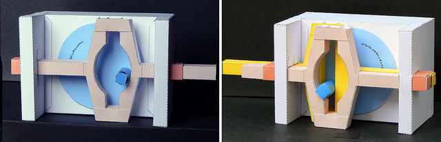
SCOTCH YOKE MECHANISM
Scotch yoke is a mechanism for converting the linear motion of a slider into rotational motion or vice-versa. Thepiston or other reciprocating part is directly coupled to a sliding yoke with a slot that engages a pin on the rotating part. The shape of the motion of the piston is a pure sine wave over time given a constant rotational speed. The double slider crank mechanism is a mechanism having two sliding pairs and two turning pairs. Scotch yoke mechanism is formed when one of the two sliding pairs in a double slider crank mechanism is fixed. It has got two turning pairs, one sliding pair and a fixed link.
[/nextpage]
[nextpage title=”Chapter 10″ ]
CHAPTER 10
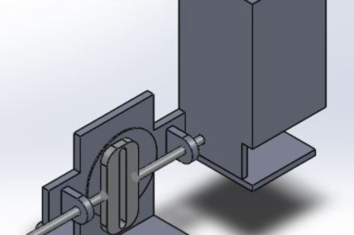
CONSTRUCTION
[sam id=”4″ codes=”true”]
The scotch yoke mechanism is constructed with iron bars. Here the crank is made in some length (say 5cm) and the yoke is also made using the same material. It is noted that the minimum length of the yoke should be double the length of the crank. The crank and yoke is connected with a pin. Iron bars are welded to both sides of the yoke to get the reciprocating motion. The yoke with the iron bars is fixed on the display board with the help of c clamp. Now the crank is welded to the end of the shaft of the motor. Now the pin on the crank is connected to the yoke. The pin used to connect yoke and crank is a bolt. The whole setup displayed in a plywood board.
[/nextpage]
[nextpage title=”Chapter 11″ ]
CHAPTER 11
WORKING
[sam id=”4″ codes=”true”]
When the power is supplied to the 12v dc motor, shaft and crank attached to the shaft start rotating. As the crank rotates the pin slides inside the yoke and also moves the yoke forward. When the crank rotates through in clockwise direction the yoke will get a displacement in the forward direction. The maximum displacement will be equal to the length of the crank. When the crank completes the next of rotation the yoke comes back to its initial position. For the next of rotation, yoke moves in the backward direction. When the crank completes a full rotation the yoke moves back to the initial position. For a complete rotation of crank the yoke moves through a length equal to double the length of the crank. The displacement of the yoke can be controlled by varying the length of the crank.
[/nextpage]
[nextpage title=”Chapter 12″ ]
CHAPTER 12
ADVANTAGES
The advantages compared to a standard crankshaft and connecting rod setup are:
[sam id=”4″ codes=”true”]
- Fewer moving parts.
- Smoother operation.
- Higher percentage of the time spent at top dead center (dwell) improving theoretical engine efficiency of constant volume combustion cycles, though actual gains have not been demonstrated.
- In an engine application,use of connecting rod is eliminated when compared to slider crank mechanism and thus reducing the vibrations produced on the connecting rod
[/nextpage]
[nextpage title=”Chapter 13″ ]
CHAPTER 13
DISADVANTAGES
The disadvantages are:
[sam id=”4″ codes=”true”]
- Rapid wear of the slot in the yoke caused by sliding friction and high contact pressures.
- Increased heat loss during combustion due to extended dwell at top dead center offsets any constant volume combustion improvements in real engines.
- Lesser percentage of the time spent at bottom dead center reducing blow down time fortwo stroke engines, when compared with a conventional piston and crankshaft mechanism.
[/nextpage]
[nextpage title=”Chapter 14″ ]
CHAPTER 14
APPLICATIONS
This setup is most commonly used in control valve actuators in high pressure oil and gas pipelines.
It has been used in various internal combustion engines, such as the Bourke engine, SyTech engine, and manyhot air engines and steam engines.
[sam id=”4″ codes=”true”]
In internal combustion engines, scotch yoke mechanism is connected to the piston instead of using the slider crank mechanism. It results in elimination of connecting rod which reduces the vibrations caused in the connecting rod. It has got extended dwell times. Experiments have shown that extended dwell time will not work well with constant volume combustion (Otto, Bourke or similar) cycles. Gains might be more apparent using a stratified direct injection (diesel or similar) cycle to reduce heat loss
[/nextpage]
[nextpage title=”Chapter 15″ ]
CHAPTER 15
CONCLUSION
[sam id=”4″ codes=”true”]
The scotch yoke mechanism is made and its advantages and disadvantages are discussed. Its motion characteristics are studied. It is concluded that this mechanism is a good choice to convert rotating motion into reciprocating motion because of fewer moving parts and smoother operation. It can be used in direct injection engines like diesel engines.
[/nextpage]


