Running Waveform in LCD : Arduino
[nextpage title=”Description” ]
[sam id=”5″ codes=”true”]
Most of the microcontrollers have a built-in ADC module which helps them in reading analog voltage inputs. This feature makes a digital device like microcontroller to be used in analog sensor applications. The microcontroller can communicate the sensed value with other devices with the help of led indications, sound generation or using the communication ports. Among all the output devices the most common and the most effective is the simple LCD module. The LCD module can be made to
display letters, numbers,
sensor values, clocks etc. They can be also configured as scrolling display also. The LCD module has separate memory where the user can store custom characters like smileys, logos etc. which can then be displayed on the LCD. The LCD display becomes most effective when the microcontroller is coded in such a way that it can display animations on the LCD module.
The LCD module makes a microcontroller based system stand-alone since it doesn’t have to rely on other devices to display the data which it would like to communicate with the user. In case of analog sensing applications the animation based display on an LCD module is most effective. If the animation includes waveform and the properties like frequency or amplitude of the waveform which can be varied based on the analog value sensed, it would be far more impressive. Small waveform displays are already found in tiny LCD modules come with media players. This particular project demonstrate how to use an
Arduino board to display a wave which resembles the sine wave in an LCD and to vary its frequency using a
potentiometer which can be replaced in future projects with any kind of analog sensor.
[/nextpage]
[nextpage title=”Description 1″ ]
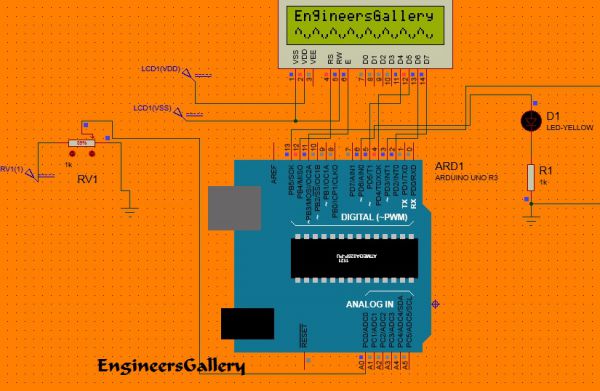
In this project the Arduino Uno board is used which is shown in circuit diagram. The programming IDE used for this project is Arduino IDE version 1.0.3 on windows operating system. The image of the Arduino Uno board and the Arduino IDE is shown in the following;
[sam id=”5″ codes=”true”]
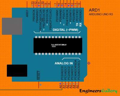
The arduino UNO board can have a maximum of eight analog pins which can be configured as analog input pins. The pins are marked in the board as A0, A1, and A2 up to A7. They are actually the input channels to the built-in ADC which can read the analog value and convert them to the digital equivalent. In this particular project the variable pin of a
potentiometer is connected to the analog pin;in this project the pin A0. The other two pins of the potentiometer is connected to the VCC and GND so that as the variable moves it can divide the entire supply voltage and provide it as the analog input voltage for the arduino board.
The built-in function in the arduino IDE analogRead() helps in reading the analog value from an analog input. The details of the functions and the method of analog read already discussed in a previous project on
how to use the analog input and output of the arduino .
The function which determines the frequency sensation of the waveform display on an LCD is the delay() function. This function is used to generate a delay between the code steps and here the function is used to set the delay between the successive displays of the custom characters. The details of the delay() function which is the basic required function in any microcontroller coding is explained in the
project on how to start with arduino.
The analog sensor value which are read with the help of the function analogRead() is provided as the input of the delay() function applying some calibrations techniques on it. The delay generated will then be equivalent to the analog voltage read from the sensor.
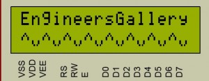
The waveform generated for display in this project with the help of custom characters that can be generated in an LCD module. The method of generating custom characters is well explained in a previous project on how to create custom characters in an LCD. The code written for this project has a function lcd.createChar() which helps to create the custom characters in an LCD screen.
The waveform is made simply by using only two custom characters, one for the positive half cycle and the other for the negative half cycle of the wave. The waveform created using the custom characters which are displayed in this project are shown in the following image.
[sam id=”5″ codes=”true”]
The bit patterns that need to be stored in the LCD to display those characters are find out using the method of drawing the pixel array and assuming the bit value for the pixel which is ON as 1 and the pixel.
The 8*5 pixel array and the corresponding binary array for the positive half cycle displayed in the project are shown in the following image;
The 8 byte long character array for the above shown custom character can be defined in the code as given below;
{
0b00100,
0b01010,
0b10001,
0b10001,
0b00000,
0b00000,
0b00000,
0b00000
};
The 8*5 pixel array and the corresponding binary array for the negative half cycle displayed in the project are shown in the following image;
[sam id=”3″ codes=”true”]
The 8 byte long character array for the above shown custom character can be defined in the code as given below;
{
0b00000,
0b00000,
0b00000,
0b00000,
0b10001,
0b10001,
0b01010,
0b00100
};
The code is written in such a way that it first displays the positive half cycle followed by the negative half cycle in the entire second row of the LCD. In then waits for a particular time which depends on the voltage read from the sensor. The delay is determined with the help of the following equation.
(outputvalue * 5)/255 + 1) * 75
In the above equation the value 75 is the minimum delay in milliseconds, which is then multiplied by the voltage factor from the sensor. The ‘outputvalue’ is the ADC value read value which can then be written into any analog output pin and is in the range of 0 to 255. The output value is divided by 255 and then added with 1 so that the entire multiplication factor with the delay 75 millisecond will be in the range of 1 to 6. Hence the minimum delay is 75 milliseconds and the maximum delay is 75*6 milliseconds.
The delay is generated by calling the built-in function delay() as given in the following statement
delay(((outputvalue * 5)/255 + 1) * 75);
Once done with the coding one can verify and upload the code to the Arduino board. Now as the potentiometer is varied one can find that the speed of the waveform which resembles the sine wave is varying.
[/nextpage]
[nextpage title=”Circuit Diagram” ]
[/nextpage]
[nextpage title=”Code” ]
[sam id=”5″ codes=”true”]
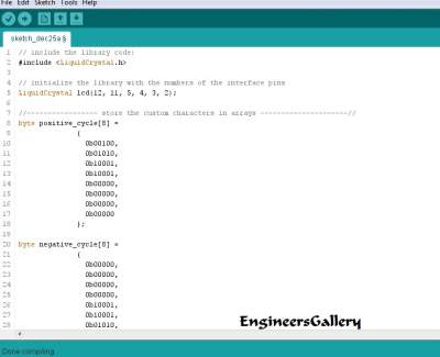
[message_box title=”CODE” color=”red”]// include the library code:
#include <LiquidCrystal.h>
// initialize the library with the numbers of the interface pins
LiquidCrystal lcd(12, 11, 5, 4, 3, 2);
//—————– store the custom characters in arrays ———————//
byte positive_cycle[8] =
{
0b00100,
0b01010,
0b10001,
0b10001,
0b00000,
0b00000,
0b00000,
0b00000
};
byte negative_cycle[8] =
{
0b00000,
0b00000,
0b00000,
0b00000,
0b10001,
0b10001,
0b01010,
0b00100
};
//—————– store the custom characters in arrays ———————//
// give the LED pin a name:
int led = 6;
int i = 0;
const int analogInPin = A0; // Analog input pin that the potentiometer is attached to
int potvalue = 0;
int outputvalue = 0;
void setup()
{
//—- create custom characters —-//
lcd.createChar(1, positive_cycle);
lcd.createChar(2, negative_cycle);
//—- create custom characters —-//
// initialize the led pin as an output.
pinMode(led, OUTPUT);
// set up the lcd’s number of columns and rows:
lcd.begin(16, 2);
lcd.print(“EngineersGallery”);
delay(2000);
}
void loop()
{
// read the analog in value:
potvalue = analogRead(analogInPin);
// map it to the range of the analog out:
outputvalue = map(potvalue, 0, 1023, 0, 255);
lcd.setCursor(0, 1);
for(i = 0; i < 8; i ++)
{
lcd.write(1);
lcd.write(2);
}
//—- blink LED —–//
digitalWrite(led, HIGH);
delay(((outputvalue * 5)/255 + 1) * 75);
digitalWrite(led, LOW);
delay(((outputvalue * 5)/255 + 1) * 75);
//—- blink LED —–//
lcd.setCursor(0, 1);
for(i = 0; i < 8; i ++)
{
lcd.write(2);
lcd.write(1);
}
//—- blink LED —–//
// digitalWrite(led, HIGH);
delay(((outputvalue * 5)/255 + 1) * 75);
// digitalWrite(led, LOW);
delay(((outputvalue * 5)/255 + 1) * 75);
//—- blink LED —–//
}[/message_box]
[sam id=”5″ codes=”true”]
[/nextpage]


