

Reverted Gear Train
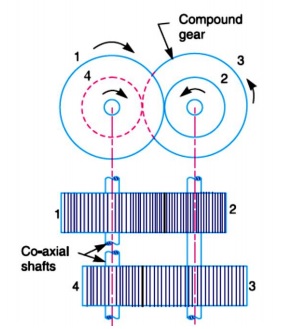
When the axes of the first gear (i.e. first driver) and the last gear (i.e. last driven or follower) are co-axial, then the gear train is known as reverted gear train as shown in Fig. 1.
We see that gear 1 (i.e. first driver) drives the gear 2 (i.e. first driven or follower) in the opposite direction. Since the gears 2 and 3 are mounted on the same shaft, therefore they form a compound gear and the gear 3 will rotate in the same direction as that of gear 2. The gear 3 (which is now the second driver) drives the gear 4 (i.e. the last driven or follower) in the same direction as that of gear 1. Thus we see that in a reverted gear train, the motion of the first gear and the last gear is like.
Let T1 = Number of teeth on gear 1,
r1 = Pitch circle radius of gear 1, and
N1 = Speed of gear 1 in r.p.m.
Similarly,
T2, T3, T4 = Number of teeth on respective gears,
r2, r3, r4 = Pitch circle radii of respective gears, and
N2, N3, N4 = Speed of respective gears in r.p.m.
Since the distance between the centers of the shafts of gears 1 and 2 as well as gears 3 and 4 is same, therefore
![]()
Also, the circular pitch or module of all the gears is assumed to be same, therefore number of teeth on each gear is directly proportional to its circumference or radius.
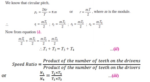
From equations (i), (ii) and (iii), we can determine the number of teeth on each gear for the given center distance, speed ratio and module only when the number of teeth on one gear is chosen arbitrarily. The reverted gear trains are used in automotive transmissions, lathe back gears, industrial speed reducers, and in clocks (where the minute and hour hand shafts are co-axial).


