

[nextpage title=”Summary” ]
Summary
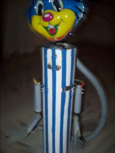
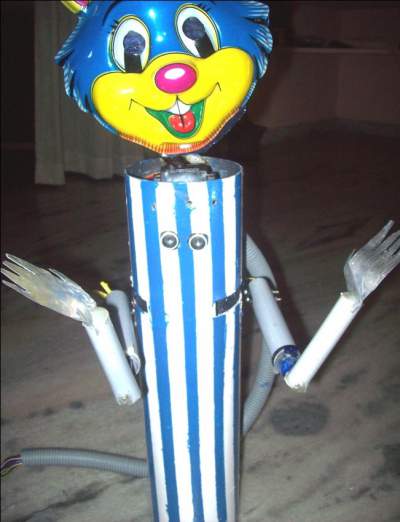
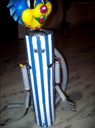
One of our follower send us His work in Arduino. He made One robo which welcomes guest in traditional Indian way.
Here is the detail which he sent us.
[sam id=”3″ codes=”true”]
Introduction: This project introduces a model based approach for human recognition and reception by designing simple robot that can scan the obstacles that are observed in its vicinity and wish them politely. This robot finds application in offices, malls, parks and functions where it can attract people. The robot rotates its head at an angle of 0̊ to 180˚ and scans obstacles and if it scans any people/obstacle that appears within its range, then it wishes “Namaste”with hand movemnets – which is an Indian traditional method of wishing people.
This project provides the design of a simple low cost service robot which acts as a good welcoming host.
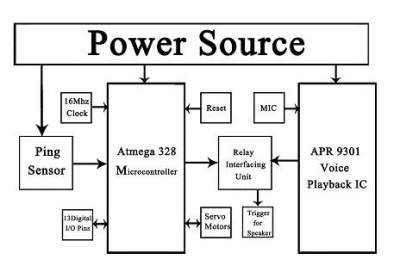
Block Diagram Of The Robot:
[sam id=”6″ codes=”true”]
[/nextpage]
[nextpage title=”Equipment Required” ]
Equipment Required:
- Arduino Uno board (Atmega328)
- Ping Sensor HC-SR04
- Relay (5v,100Ω)
- Apr 9300 voice playback development board.
[sam id=”6″ codes=”true”]
Introduction to Components:
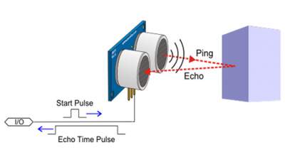
Ping sensor (Ultrasonic sensor)
Ultrasonic ranging module HC – SR04 provides 2cm – 400cm non-contact measurement function, the ranging accuracy can reach to 3mm. The modules includes ultrasonic transmitters, receiver and control circuit. Simple working of the ping sensor is shown below.
[sam id=”5″ codes=”true”]
Wire connecting direct as following:
- 5V Supply
- Trigger Pulse Input to arduino Uno pin “3 ”
- Echo Pulse Output to arduino Uno pin “ 12”
- 0V Ground
[/nextpage]
[nextpage title=”Circuit Diagram” ]
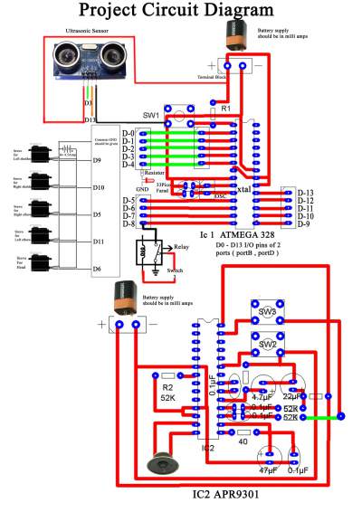
Circuit Diagram.
[sam id=”6″ codes=”true”]
[sam id=”5″ codes=”true”]
[/nextpage]
[nextpage title=”Description” ]
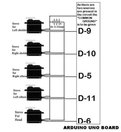
Interfacing SERVO with ARDUINO:
Servo motors are dc motors with a servo mechanism that lets us control the precise position of the Shaft. A servo mechanism is a error correction mechanism that senses the negative error and applies a correction accordingly. There are many types of Servo Motors available depending upon applications these is used. They are used in areas requiring position control. While the basic working of all the servo motors is almost similar, for the scope of this tutorial we shall stick to discussing RC Servo Motors or the type of Servo motors used in Robotics / Radio Control Projects.
[sam id=”6″ codes=”true”]
NOTE: Here in the below circuit diagram pins D5, D6, D9, D10, D11 are the Digital I/O pins that are present in the Arduino board.
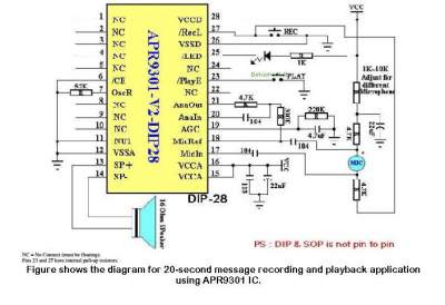
Circuit for Speech playback: Here this module is used for the voice playback and a single note is played repeatedly when the push to ON switch is pressed (PIN 23).
As the value of the resistor varies that which is placed in between in 6 & 7 is replaced with the resistor values i.e. 38k, 52k, 67k, and 89k. There the sampling frequency is also varied so that there is an increase in the record delay increases as shown in the above tabular form.
[sam id=”5″ codes=”true”]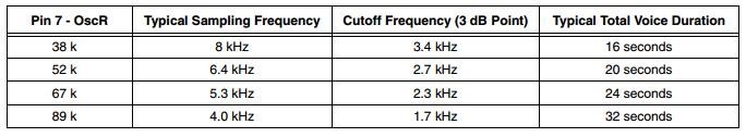
[/nextpage]
[nextpage title=”Source Code” ]
[sam id=”6″ codes=”true”]
[message_box title=”Source Code” color=”red”]
#include <Servo.h> //Initiating the header files and defining the pins
#define trigPin 3
#define echoPin 12
#define led 4
#define relay 8
Servo sl; //Attaching the objects
Servo head;
Servo sr;
Servo el;
Servo er;
int posh=0;
int posl=0;
int posr=0;
void setup()
{
sl.attach(9); //Attaching the servos to the arduino I/O pins
sr.attach(10);
el.attach(11);
er.attach(5);
head.attach(6);
Serial.begin (9600);
pinMode(trigPin, OUTPUT); // Defining the I/O pins
pinMode(relay, OUTPUT);
pinMode(echoPin, INPUT);
pinMode(led, OUTPUT);
}
void loop()
{
for(posh = 0;posh <= 180; posh +=1)
{
head.write(posh);
adam();
//adding the function to check in the every step of the head turn process
delay(15);
}
for(posh = 180;posh >=0; posh -=1)
{
head.write(posh);
adam();
//adding the function to check in the every step of the head turn process
delay(15);
}
}
void adam() //Calling back the function.
{
long duration, distance;
digitalWrite(trigPin, LOW);
delayMicroseconds(2);
digitalWrite(trigPin, HIGH);
delayMicroseconds(10);
digitalWrite(trigPin, LOW);
duration = pulseIn(echoPin, HIGH);
distance = (duration/2) / 29.1;
if (distance < 3)
{
// This is where the LED On/Off happens
digitalWrite(led,HIGH);
// When the Red condition is met, the Green LED should turn off
Serial.println(“WELCOME”);
head.write(90);
for(posl = 0, posr = 180; posl <= 90 ; posl +=1) //shoulder up
{
sl.write(posl);
sr.write(posr);
posr -=1;
delay(15);
}
for(posr = 0,posl=180; posr <= 45; posr +=1) // elbow close
{
er.write(posr);
el.write(posl);
posl -=1;
delay(15);
}
delay(3000); // A delay of 3 seconds is added in Namaste position
for(posr = 45,posl=135; posr >= 0; posr -=1) //elbow open
{
er.write(posr);
el.write(posl);
posl +=1;
delay(15);
}
for(posr = 90,posl= 90; posr <= 180; posr +=1) //shoulder down
{
sr.write(posr);
sl.write(posl);
posl -=1;
delay(15);
}
digitalWrite(relay,HIGH); //Relay is activated for 1 second
delay(1000);
digitalWrite(relay,LOW);
delay(10000);
}
else //In all the remaining cases LED is OFF
{
digitalWrite(led,LOW);
}
}
[/message_box]
[sam id=”5″ codes=”true”]
[/nextpage]
[nextpage title=”Simulated Results” ]
SIMULATED RESULTS:
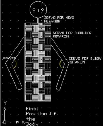
- The fig1 represent the initial position of the robot and in this motion the servos are in OFF state expect the servo which is used for the head rotation mechanism.
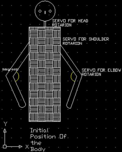
Here in the above figure shows that the robot is in initial state i.e. the servos that which are present at the elbow and servos present at the shoulder are in OFF state. But the servo present at the top which is used for the rotation of the head pans from left to right which states that it is in HIGH state. This moment of the head indicates that the robot is searching for an obstacle. When any obstacle is sensed by the PING sensor the head position is said to be back to 90 degree angle and the turns to OFF state. Then the reaming servos at the shoulder and the elbow side are in HIGH state i.e. the signal line is activated for the reaming 4 servos which are connected to the Arduino Digital pins D5,D9,D10,D11 are said to be in
ON state.
[sam id=”5″ codes=”true”]
- 2nd state of the robot:

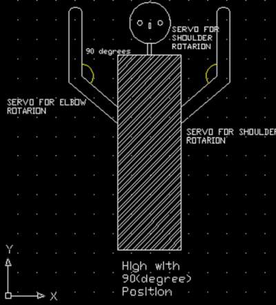
This is the second state of the robot and here the head servo that is the line ‘D5’ is in LOW state. The pins (D9, D10) are kept in HIGH state so that the left side shoulder and the right servo used for the uplift of the shoulder is HIGH with an angle of 90 degrees and then the servos that which are used for the elbow movement activates.
- 3rd state of the robot:
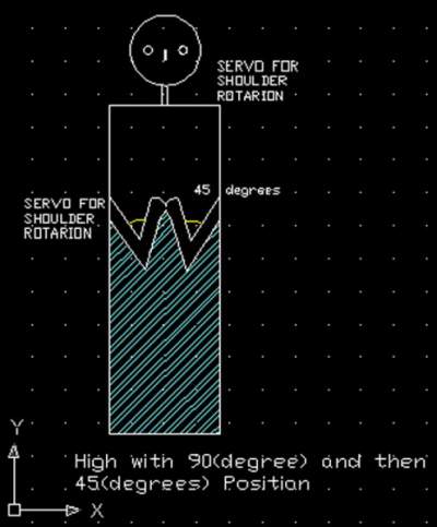
The below figure is the position of the robot this is the actual desired position of the robot. This position indicates the Namaste position after the 90 degrees of high motion from the shoulders then the action of the elbow movement starts and here in the Namaste position there is a delay of ‘3’ seconds is applied in that position. The digital pins that are used for the elbow movement are (D5, D11). At all these cases the position of the head is in 90 degrees and basically in the OFF state. All these actions depend upon the signal line that comes from the Arduino Uno board.
- 4th state of the robot:

Again the 4th position is matched with the 2nd position that is the after the 3 seconds of delay from the Namaste position it is back to the 2nd position as observed. The -45 degree of operation is performed.
[sam id=”3″ codes=”true”]
5th state of the robot:
This is the final view that is observed all the servo lines are set to zero (D5,D11,D10,D9) are down to OFF state. And the ‘D6’ digital pin is HIGH that which is used for the head rotation is performed and the PING again starts searching for the obstacle panning from left to right.
After all the 5 states then finally the relay pin is triggered for 1 second so that the playback IC is turned ON and the voice note that is saved in the IC is played through the speaker.
[sam id=”5″ codes=”true”]
Firmware’s Used:
- Auduino for developing the program
- PCB wizard and Photoshop for designing the circuit
- Autocad for the simulated results
[/nextpage]
[sam id=”3″ codes=”true”]
Project submitted by :
Vallikat.Sai Krishna
[sam id=”3″ codes=”true”]
NRI INSTITUTE OF TECHNOLOGY, ECE Department, Vijayawada, Andhra Pradesh, India
[sam id=”3″ codes=”true”]


