

Multimeter Tutorial: How to test Continuity
Continuity Test is a method to check current flow across any metallic path. Through this test, any unwanted circuit breaks or shorted connections can be put to verification. Continuity can be tested between any two circuit connections.
Apparatus: Multimeter, connecting probes, circuit board.
Step 1: Take the circuit board of which you want to test the continuity.
Step 2: Map the traced tracks and corresponding electronic components soldered on them.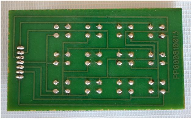
Step 3: Turn the knob on the multimeter towards the continuity section
[tie_slideshow]
[tie_slide] Multimeter Tutorial: How to Test LED [/tie_slide]
[tie_slide] Multimeter Tutorial: How to Test a Transistor [/tie_slide]
[tie_slide] Multimeter Tutorial: How to Test and Measure Resistance [/tie_slide]
[/tie_slideshow]
Step 4: Testing leads should be connected to the multimeter in the same manner as shown in the image below. 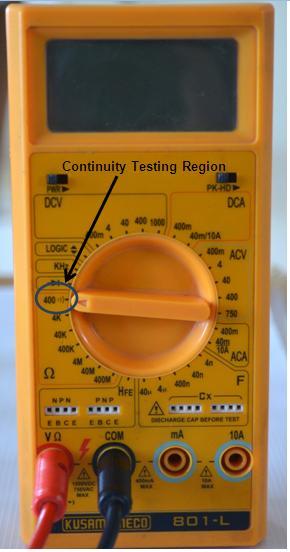
Different multimeters have different location of continuity section. In this model it’s on 400 ohm.
Step 5:Select the metallic path of which you want to check the continuity and place one testing lead at the starting terminal and another at the other.
Step 6: After placing the leads on their position the multimeter will produce a continuous beep sound indicating that track is continuous and there is no breakage in the track.


