MULTI-STAGE HYDRO-ELECTRIC POWER PLANT | Buy Mechanical Project
SYNOPSIS
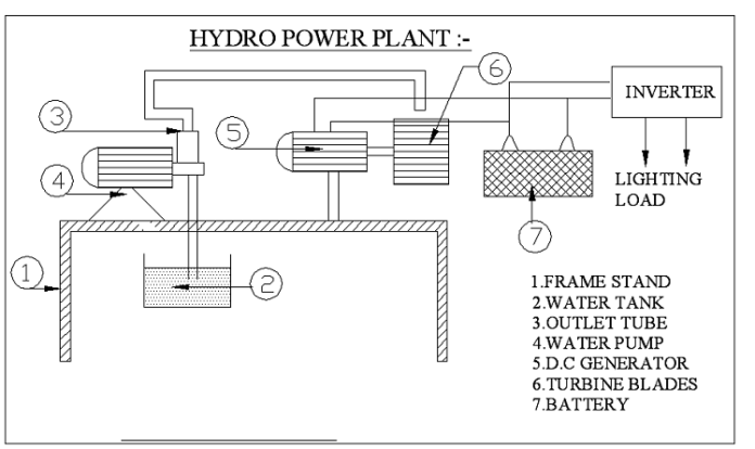
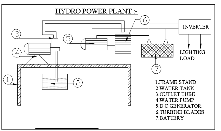
Water turbines convert Mechanical rotary energy into Electrical energy. A mechanical interface, consisting of a step-up gear, water Pump and a suitable coupling transmits the energy to an electrical generator. The output of this generator is connected to the Battery or system grid. The battery is connected to the inverter. The inverter is used to convert DC voltages to AC voltages. The load is drawn current from the inverter.
- Generator
- Mains haft with Leafs
- Gear Wheel Arrangement
Water power ratings can be divided into three convenient grouping, small to 1kW, medium to 50 kW and large 200 kW to megawatt frame size.
INTRODUCTION
MAN AND ENERGY:
Man has needed and used energy at an increasing rate for its sustenance and well being ever since he came on the earth a few million years ago. Primitive man required energy primarily in the form of food. He derived this by eating plants or animals, which he hunted. Subsequently he discovered fire and his energy needs increased as he started to make use of wood and other bio mass to supply the energy needs for cooking as well as agriculture. He added a mew dimension to the use of energy by domesticating and training animals to work for him.
With further demand for energy, man began to use the wind for sailing ships and for driving windmills, and the force of failing water to turn water wheels. Till this time, it would not be wrong to say that the sun was supplying all the energy needs of man either directly or indirectly and that man was using only renewable sources of energy.
WORKING PRINCIPLE
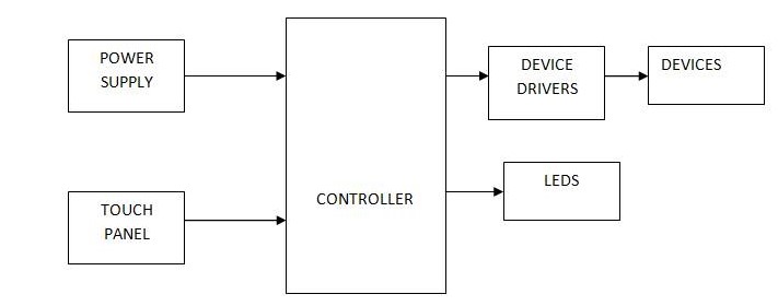
The block diagram of multi-stage hydro power plant is consisting of a water tank, 12 voltage batteries, an inverter and a florescent lamp. As we studied from the generator gives a D.C. output of 12V this D.C. output is not always constant there is some variation in this D.C. output this cannot be given to the battery storage it may weaken the life of the battery. So in order to get constant D.C. output and also to avoid the reverse flow of current to the panel in the case of no load a charge controller have been used this help us to allow only the constant voltage of 12V D.C. to the battery and also it act as an blocking diode and protect the motor principle.
By this way the battery gets charged then this D.C. storage is given to an inverter this inverter inverts 12V D.C. to input in to AC output, step upped in to 230V.The 230V AC supply is given to the supply to the lamp. The lamp used for street lighting is 230V, 50 Hz, single-phase supply.
ADVANTAGES AND DISADVANTAGES
ADVANTAGES
- Power is produced by the simply the water pumping system
- This is a Non-conventional system
- Battery is used to store the generated power
- Low cost power generation system
DISADVANTAGES
- Only applicable for the particular place.
- Initial cost of this arrangement is high.
APPLICATIONS
Direct heat applications
Mechanical motion derived from water power can be used to drive heat pumps or to produce heat from the friction of solid materials, or by the churning of water or other fluids, or in other cases, by the use of centrifugal or other types of pumps in combination with restrictive orifices that produces heat from friction and turbulence when the working fluid flows through them. This heat may then be stored in materials having a high heat capacity, such as water, stones, eutectic salts, etc.,
A home heating system that uses a water powered pump and a restrictive orifice to derive direct heat for a building, without first generating electricity also has been developed.
Electric Generation Applications:
Water power can be used in centralized utility applications to drive synchronous A.C. electrical generators. In such applications the energy is fed directly into power networks through voltage step-up transformers.
This unit can be integrated with existing multi-stage hydro electrical networks and used in a “water-saver” mode of operation. When the water is blowing, electrical an amount equal to the being can reduce generation at the multi-stage hydroelectric plants in the network produced by this unit. Thus, the water turbines supply part of the network load that is ordinarily produced by the multi-stage hydroelectric generators. Under these conditions some of the water that would have been used by the multi-stage hydroelectric plant to supply the load is saved in the reservoir and made available for later use when the water is not blowing.

