

Methods of Failure of Knuckle Joint :
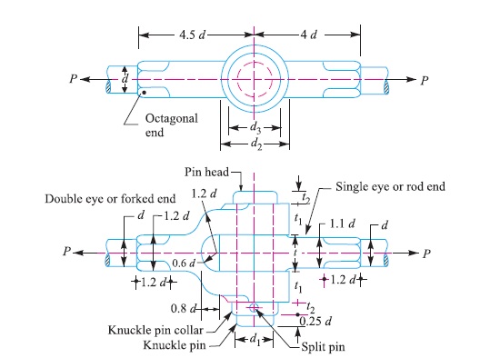
Consider a knuckle joint as shown in Fig. 3.
Let P = Tensile load acting on the rod,
d = Diameter of the rod,
d1 = Diameter of the pin,
d2 = Outer diameter of eye,
t = Thickness of single eye,
t1 = Thickness of fork.
σt , τ and σc = Permissible stresses for the joint material in tension, shear and crushing respectively.
In determining the strength of the joint for the various methods of failure, it is assumed that
1. There is no stress concentration, and
2. The load is uniformly distributed over each part of the joint.
Due to these assumptions, the strengths are approximate, however they serve to indicate a well proportioned joint. Following are the various methods of Failure of Knuckle Joint :
1. Failure of the solid rod in tension
Since the rods are subjected to direct tensile load, therefore tensile strength of the rod,
= (π × d^2 × σt) / 4
Equating this to the load (P) acting on the rod, we have
P = (π × d^2 × σt) / 4
From this equation, diameter of the rod ( d ) is obtained.
2. Failure of the knuckle pin in shear
Since the pin is in double shear, therefore cross-sectional area of the pin under shearing
= 2 × [(π × d1^2 )/4]
and the shear strength of the pin
= {2 × [(π × d1^2 )/4]} τ
Equating this to the load (P) acting on the rod, we have
P = {2 × [(π × d1^2 )/4]} τ
From this equation, diameter of the knuckle pin (d1) is obtained. This assumes that there is no slack and clearance between the pin and the fork and hence there is no bending of the pin. But, in actual practice, the knuckle pin is loose in forks in order to permit angular movement of one with respect to the other, therefore the pin is subjected to bending in addition to shearing. By making the diameter of knuckle pin equal to the diameter of the rod (i.e., d1 = d), a margin of strength is provided to allow for the bending of the pin.
In case, the stress due to bending is taken into account, it is assumed that the load on the pin is uniformly distributed along the middle portion (i.e. the eye end) and varies uniformly over the forks as shown in Fig. 4. Thus in the forks, a load P/2 acts through a distance of t1 / 3 from the inner edge and the bending moment will be maximum at the centre of the pin. The value of maximum bending moment is given by
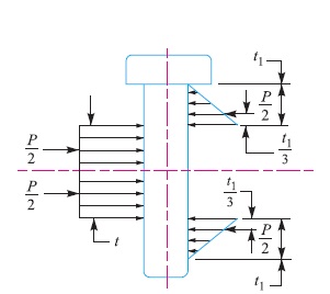
M = P/2 [(t1/3) + (t/2)] – [(P/2)(t/4)]
= P/2 {(t1/3) + (t/2) – (t/4)}
= P/2 {(t1/3) + (t/4)}
and section modulus, Z = {π (d1)^3} / 32
∴ Maximum bending (tensile) stress,
σt = M/Z = [P/2 {(t1/3) + (t/4)}] / [{π (d1)^3} / 32]
From this expression, the value of d1 may be obtained.
3. Failure of the single eye or rod end in tension
The single eye or rod end may tear off due to the tensile load. We know that area resisting tearing = (d2 – d1) t
∴ Tearing strength of single eye or rod end
= (d2 – d1) t × σt
Equating this to the load (P) we have
P = (d2 – d1) t × σt
From this equation, the induced tensile stress (σt) for the single eye or rod end may be checked.
In case the induced tensile stress is more than the allowable working stress, then increase the outer diameter of the eye (d2).
4. Failure of the single eye or rod end in shearing
The single eye or rod end may fail in shearing due to tensile load. We know that area resisting shearing = (d2 – d1) t
∴ Shearing strength of single eye or rod end
= (d2 – d1) t × τ
Equating this to the load (P), we have
P = (d2 – d1) t × τ
From this equation, the induced shear stress (τ) for the single eye or rod end may be checked.
5. Failure of the single eye or rod end in crushing
The single eye or pin may fail in crushing due to the tensile load. We know that area resisting crushing = d1 × t
∴ Crushing strength of single eye or rod end
= d1 × t × σc
Equating this to the load (P), we have
∴ P = d1 × t × σc
From this equation, the induced crushing stress (σc) for the single eye or pin may be checked. In case the induced crushing stress in more than the allowable working stress, then increase the thickness of the single eye (t).
6. Failure of the forked end in tension
The forked end or double eye may fail in tension due to the tensile load. We know that area resisting tearing
= (d2 – d1) × 2 t1
∴ Tearing strength of the forked end
= (d2 – d1) × 2 t1 × σt
Equating this to the load (P), we have
P = (d2 – d1) × 2t1 × σt
From this equation, the induced tensile stress for the forked end may be checked.
7. Failure of the forked end in shear
The forked end may fail in shearing due to the tensile load. We know that area resisting shearing
= (d2 – d1) × 2t1
∴ Shearing strength of the forked end
= (d2 – d1) × 2t1 × τ
Equating this to the load (P), we have
P = (d2 – d1) × 2t1 × τ
From this equation, the induced shear stress for the forked end may be checked. In case, the induced shear stress is more than the allowable working stress, then thickness of the fork (t1) is increased.
8. Failure of the forked end in crushing
The forked end or pin may fail in crushing due to the tensile load. We know that area resisting crushing = d1 × 2 t1
∴ Crushing strength of the forked end
= d1 × 2 t1 × σc
Equating this to the load (P), we have
P = d1 × 2 t1 × σc
From this equation, the induced crushing stress for the forked end may be checked.
Note: From the above failures of the joint, we see that the thickness of fork (t1) should be equal to half the thickness of single eye (t / 2). But, in actual practice t1 > t / 2 in order to prevent deflection or spreading of the forks which would introduce excessive bending of pin.
Reference A Textbook of a Machine Design by R.S. Khurmi and J.K. Gupta


