Introduction:
This is the very interesting project in the series of doorbell or sound generator. Most available doorbell in the market use AC mains with step-down transformer to operate which warms up the apparatus used (transformer etc.) These doorbells available in market also use some amount of energy unnecessarily and main problem is it does not work in lack of ac power i.e. in the time of power gone.
The circuit published in this site is simple and use 3V DC battery to operate instead of AC mains, with good quality sound. It has features of shut-off to stop the drainage of stand by current thus increasing battery life. It also have feature of echo effect which is pleasing and quite enchanting.
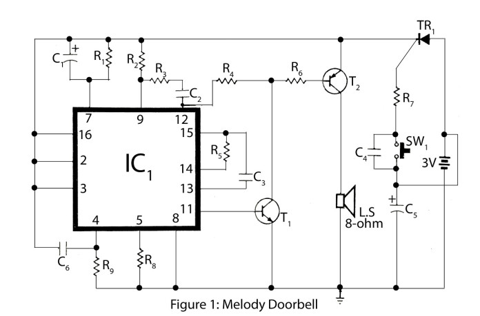
Circuit description of melody doorbell
The tryristor used in the circuit melody doorbell is acts as an electronics switch. Capacitor C4 get charge when switch SW1 is pressed and surge current from speaker keeps tryristor on.
Signal from pin 11 is amplified by transistor T1 and given to pin 12 through resistor R4 and further to pin 9 through capacitor C2 and resistor R3. Here transistor T1 & T2 is paired for further amplification of output signal and fed to speaker for output. Resistor R1 & R5 and capacitor C1 and C5 determine decay period for the electronics at pin 7 and 15 respectively set the speed and tone of the melody.
PARTS LIST
Resistors (all ¼-watt, ± 5% Carbon)
- R1, R2 = 100 KΩ
- R3 = 56 KΩ
- R4 = 1 MΩ
- R5 = 68 KΩ
- R6 = 22 Ω
- R7 = 1 KΩ
- R8 = 2.2 KΩ
- R9 = 330 KΩ
Capacitors
- C1 = 4.7 µF/16V
- C2 = 100 PF
- C3 = 47 PF
- C4 = 0.1 µF
- C5 = 1000 µF/16V
- C6 = 100 PF
Semiconductors
- IC1 = CIC 4822E
- T1 = BC548
- T2 = SK100
- TR1 = 2N6565
Miscellaneous
- Speaker 8 Ω
- SW1 = Push-to-on switch
- 3V battery


