

Introduction:
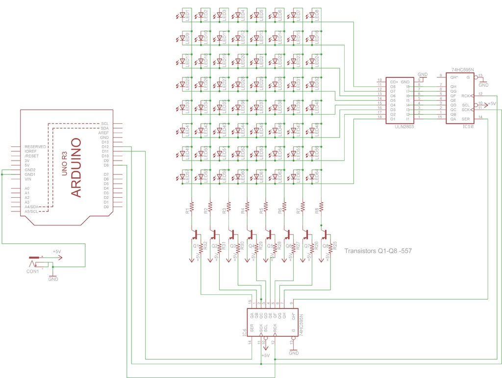
In this project, you will use two sets of shift registers. These will be connected to the rows and
columns of the dot matrix display. You will then show a simple object, or sprite, on the display and
animate it. The main aim of this project is to show you how a dot matrix display works and introduce the
concept of multiplexing because this is an invaluable skill to have.
Step 1: Things Required
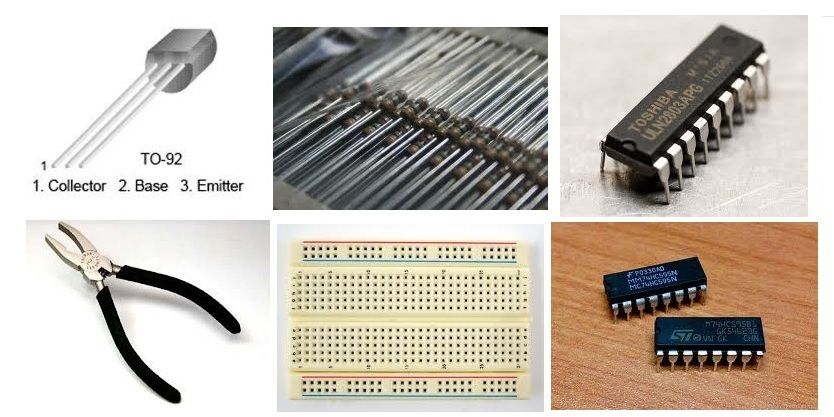
for this project you will require -:
1. 1 LED matrix
2. 8 resistors 1k ohm
3. 8 557 transistors
4. 1 ULN2803 IC
5 Arduino
6. 2 74HC595 shift register
7. 2 Bread board
8. Connecting Wires
Step 2: Working
matrix such that either the anode or cathode of each LED is common in each row. In other words, in a
common anode LED dot matrix unit, each row of LEDs would have all of their anodes in that row wired
together. The cathodes of the LEDs would all be wired together in each column. The reason for this will
become apparent soon.
A typical single color 8×8 dot matrix unit will have 16 pins, 8 for each row and 8 for each column.
The reason the rows and columns are all wired together is to minimize the number of pins required.
If this were not the case, a single color 8×8 dot matrix unit would need 65 pins, one for each LED and a
common anode or cathode connector. By wiring the rows and columns together, only 16 pins are
required.However, this now poses a problem if you want a particular LED to light in a certain position. If, for
example, you had a common anode unit and wanted to light the LED at X, Y position 5, 3 (5th column,
3rd row), then you would apply a current to the 3rd Row and ground the 5th column pin.
The LED in the 5th column and 3rd row would now light.
Now let’s imagine that you want to also light the LED at column 3, row 6. So you apply a current to
the 6th row and ground the 3rd column pin. The LED at column 3, row 6 now illuminates. But wait…the
LEDs at column 3, row 6 and column 5, row 6 have also lit up.
This is because you are applying power to row 3 and 6 and grounding columns 3 and 5. You can’t
turn off the unwanted LEDs without turning off the ones you want on. It would appear that there is no
way you can light just the two required LEDs with the rows and columns wired together as they are. The
only way this would work would be to have a separate pinout for each LED, meaning the number of pins
would jump from 16 to 65. A 65-pin dot matrix unit would be very hard to wire up and control because
you’d need a microcontroller with at least 64 digital outputs.
Is there a way to get around this problem? Yes there is, and it is called multiplexing (or muxing).
Multiplexing is the technique of switching one row of the display on at a time. By selecting the column
that contains the row that contains the LED that you want to be lit, and then turning the power to that
row on (or the other way round for common cathode displays), the chosen LEDs in that row will
illuminate. That row is then turned off and the next row is turned on, again with the appropriate
columns chosen and the LEDs in the second row will now illuminate. Repeat with each row till you get to
the bottom and then start again at the top.
If this is done fast enough (at more than 100Hz, or 100 times per second) then the phenomenon of
persistence of vision (where an afterimage remains on the retina for approx 1/25th of a second) will mean
that the display will appear to be steady, even though each row is turned on and off in sequence.
By using this technique, you get around the problem of displaying individual LEDs without the
other LEDs in the same column or row also being lit.
By scanning down the rows and illuminating the respective LEDs in each column of that row and
doing this very fast (more than 100Hz) the human eye will perceive the image as steady and the image of
the heart will be recognizable in the LED pattern.
You are using this multiplexing technique in the Project’s code. That’s how you’re to display the
heart animation without also displaying extraneous LEDs.
Step 3:
you have to calculate the value of the resistors you can use
You should first get some specs on your LEDs, you should know their forward voltage and forward current, you can get this info from the datasheet. The circuit operates on 5V so your Source voltage is 5V which can be obtained from a 5v adapter
Download the original file to see the schematics better.(press the “i” icon in the top left corner of the picture)
Step 4: Making it Work
CODE:
int latchPin = 8; //Pin connected to Pin 12 of 74HC595 (Latch)
int clockPin = 12; //Pin connected to Pin 11 of 74HC595 (Clock)
int dataPin = 11; //Pin connected to Pin 14 of 74HC595 (Data)
String Str;
byte alphabets[][8] =
{ {0,0,0,0,0},
{0,56,125,56,0},//!
{80,96,0,80,96},//”
{20,127,20,127,20},//#
{18,42,127,42,36},//$
{98,100,8,19,35},//%
{54,73,85,34,5},//&
{0,80,96,0,0},//'(7)
{0,28,34,65,0},//(
{0,65,34,28,0},//)
{20,8,62,8,20},//*
{8,8,62,8,8},//+
{0,5,6,0,0},//,(12)
{8,8,8,8,8},//-
{0,3,3,0,0},//.(14)
{2,4,8,16,32},///
{62,69,73,81,62},//0
{17,33,127,1,1},//1
{33,67,69,73,49},//2
{34,65,73,73,54},//3
{12,20,36,127,4},//4
{114,81,81,81,78},//5
{62,73,73,73,38},//6
{64,71,72,80,96},//7
{54,73,73,73,54},//8
{50,73,73,73,62},//9
{0,54,54,0,0},//:(26)
{0,53,54,0,0},//;(27)
{8,20,34,65,0},//<
{20,20,20,20,20},//=
{0,65,34,20,8},//>
{32,64,69,72,48},//?
{62,73,87,85,62},//@
{31, 36, 68, 36, 31},//A
{127, 73, 73, 73, 54},//B
{62, 65, 65, 65, 34},//C
{127, 65, 65, 34, 28},//D
{127, 73, 73, 65, 65},//E
{127, 72, 72, 72, 64},//F
{62, 65, 65, 69, 38},//G
{127, 8, 8, 8, 127},//H
{65, 65, 127, 65, 65},//I
{2, 1, 1, 1, 126},//J
{127, 8, 20, 34, 65},//K
{127, 1, 1, 1, 1},//L
{127, 32, 16, 32, 127},//M
{127, 16, 8, 4, 127},//N
{62, 65, 65, 65, 62},//O
{127, 72, 72, 72, 48},//P
{62, 65, 69, 66, 61},//Q
{127, 72, 76, 74, 49},//R
{50, 73, 73, 73, 38},//S
{64, 64, 127, 64, 64},//T
{126, 1, 1, 1, 126},//U
{124, 2, 1, 2, 124},//V
{126, 1, 6, 1, 126},//W
{99, 20, 8, 20, 99},//X
{96, 16, 15, 16, 96},//Y
{67, 69, 73, 81, 97},//Z
{0,127,65,65,0},//[
{32,16,8,4,2},//
{0,65,65,127,0},
{16,32,64,32,16},//^
{1,1,1,1,1},//_
{0,64,32,16,0},//`
{2,21,21,14,1},//a
{64,126,9,17,14},//b
{14,17,17,17,10},//c
{14,17,74,127,1},//d
{14,21,21,21,9},//e
{1,9,63,72,32},//f
{9,21,21,21,30},//g
{127,8,8,8,7},//h
{0,0,46,1,1},//i
{2,1,1,1,94},//j
{1,127,4,10,17},//k
{0,65,127,1,0},//l
{31,16,14,16,31},//m
{31,8,16,16,15},//n
{14,17,17,17,14},//o
{127,20,20,20,8},//p
{8,20,20,31,1},//q
{31,8,16,16,8},//r
{9,21,21,21,18},//s
{16,16,126,17,18},//t
{30,1,1,30,1},//u
{28,2,1,2,28},//v
{30,1,6,1,30},//w
{17,10,4,10,17},//x
{16,9,6,8,16},//y
{17,19,21,25,17},//z
{8,54,65,65,0},//{
{0,0,127,0,0},//|(92)
{0,65,65,54,8},//}
{32,64,32,16,32},//~
}
int M[8],ap,ai,space=0;
void setup() {
Serial.begin(9600);
pinMode(latchPin, OUTPUT); // set the 3 digital pins to outputs
pinMode(clockPin, OUTPUT);
pinMode(dataPin, OUTPUT);
//Timer1.initialize(10000); // set a timer of length 10000 microseconds
//Timer1.attachInterrupt(screenUpdate); // attach the screenUpdate function
}
void loop() {
while (Serial.available()) {
delay(10);
if (Serial.available() >0) {
char c = Serial.read();
Str+= c;}
}
for(int t=0;t<2;t++)
{
text();
ai=0;
for(byte ap=0;ap<=4;ap++)
{ M[7]=alphabets[ai][ap];
for(byte i=0;i<7;i++)
M[i]=M[i+1];
screenUpdate(250);
}
ap=0;
}
if (Str.length() >0)
{
Serial.println(Str);
Str=””;
}
}
void screenUpdate(unsigned long frametime)
{ // function to display image
unsigned long startime=millis();
while(millis()-startime<frametime)
{
byte row = B0000001; // row 1
for (byte k = 0; k < 8; k++)
{
digitalWrite(latchPin, LOW); // open latch ready to receive data
shiftIt(row); // row binary number
shiftIt(~M[k] ); // LED array (inverted)
// Close the latch, sending the data in the registers out to the matrix
digitalWrite(latchPin, HIGH);
row = row<< 1; // bitshift right
}
}
}
void shiftIt(byte dataOut) {
// Shift out 8 bits LSB first, on rising edge of clock
boolean pinState;
//clear shift register read for sending data
digitalWrite(dataPin, LOW);
// for each bit in dataOut send out a bit
for (int i=0; i<8; i++) {
//set clockPin to LOW prior to sending bit
digitalWrite(clockPin, LOW);
// if the value of DataOut and (logical AND) a bitmask
// are true, set pinState to 1 (HIGH)
if ( dataOut & (1<<i) ) {
pinState = HIGH;
}
else {
pinState = LOW;
}
//sets dataPin to HIGH or LOW depending on pinState
digitalWrite(dataPin, pinState);
//send bit out on rising edge of clock
digitalWrite(clockPin, HIGH);
digitalWrite(dataPin, LOW);
}
digitalWrite(clockPin, LOW); //stop shifting
}
void text()
{
int i=0;
while (Str[i]!=NULL)
{
ai=Str[i]-‘!’+1;
if(ai==0)
{
for(byte i=0;i<7;i++)
M[i]=M[i+1];
screenUpdate(250);
ap=5;
}
if(ai==1)
{
for(ap=1;ap<=3;ap++)
{
for(byte i=0;i<7;i++)
M[i]=M[i+1];
M[7]=alphabets[ai][ap];
screenUpdate(250);
}
ap=5;
}
if(ai==7)
{
for(ap=1;ap<=2;ap++)
{
for(byte i=0;i<7;i++)
M[i]=M[i+1];
M[7]=alphabets[ai][ap];
screenUpdate(250);
}
ap=5;
}
if(ai==12)
{
for(ap=1;ap<=3;ap++)
{
for(byte i=0;i<7;i++)
M[i]=M[i+1];
M[7]=alphabets[ai][ap];
screenUpdate(250);
}
ap=5;
}
if(ai==14)
{
for(ap=1;ap<=3;ap++)
{
for(byte i=0;i<7;i++)
M[i]=M[i+1];
M[7]=alphabets[ai][ap];
screenUpdate(250);
}
ap=5;
}
if(ai==26)
{
for(ap=1;ap<=3;ap++)
{
for(byte i=0;i<7;i++)
M[i]=M[i+1];
M[7]=alphabets[ai][ap];
screenUpdate(250);
}
ap=5;
}
if(ai==27)
{
for(ap=1;ap<=3;ap++)
{
for(byte i=0;i<7;i++)
M[i]=M[i+1];
M[7]=alphabets[ai][ap];
screenUpdate(250);
}
ap=5;
}
if(ai==92)
{
for(ap=2;ap<=3;ap++)
{
for(byte i=0;i<7;i++)
M[i]=M[i+1];
M[7]=alphabets[ai][ap];
screenUpdate(250);
}
ap=5;
}
for(int i=0;i<7;i++)
{
M[i]=M[i+1];
}
if(ap==5)
{
M[7]=0;
ap=0;
ai=Str[++i]-‘!’+1;
}
else
{
M[7]=alphabets[ai][ap++];
}
screenUpdate(250);
}
}
Step 5: All Done !!!!!!!!!


