

Hello friends ,
Use of this article in our temperature sensor is a home automation system and factory can establish many times used their control and fan control system with temperature sensor will continue to consistently use easily for your system Although made with easy connection on dnyarduino take it pm after a series Arduino and your system control .dnyarduino create a try as it is known where installed in your head in platform .dnyarduino link are trying to as much as possible explanation we can but also internal connections and test sets of our friends who are curious about how to make easy connections from this site: http://www.mikrouygulamalar.com/#!dnyarduino / cwc2 downloading the user manual can solve those attached to the head ..
When it comes to the expression experiments,
Try a temperature sensor, a DC motor, an LCD and an external power supply 5V output on .dnyarduino directly from there mot the joints 5V even come. but I have an external power source using the preferred I reason studies wave is on the motor current drawn by the LCD for to create working with 5V engine is sufficient.
Done in the required automation:
- The temperature of the ambient temperature sensor that LCD screen.
- The control part of the year as soon as the ambient temperature exceeds 30 degrees, the DC motor is running.
- DC motor assumes the cooler.
- Currently the engine stops it again falls below 30 degrees.
Circuits and links you want to share fully in order to explain the picture which shows the circuit diagram and the connection you want to give information about how to use and connection of the parts slowly here ..
CONNECTIONS TIME CHART:
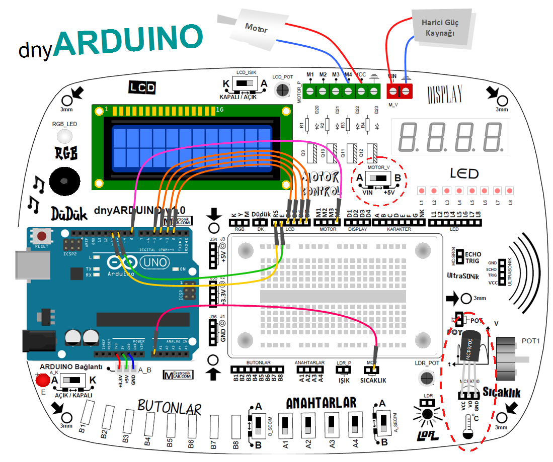
LCD CONNECTIONS:
dnyarduino on 2 lines, 16 characters limit column with LCD. LCDs user router is very often used to display information or numerical data variables.
LCD pins:
1 GND 2-VCC LCD Contrast 3-pin, 4-RESET 5-literacy, 6-ENABLE Pini, unused pins 7-10, 11-DATA4,12-DATA5,13-DATA6,14, DATA7,15 VCC- back lighting, 16-backlight GND is.
TEMPERATURE SENSOR (MCP9700):
- The sensor operates from -40 to 125 degrees.
- 1 shows a 10mV output values to the degree.
I’m going to try to understand the calculation of the temperature sensor in the Arduino code.
float temperature = ((float) analog read (A0) * 5.0 / 1024.0) – 0.5;
temperature = temperature / 0.01;
As we know, when the analog value reading shows a value between 0-1024. This new 0V to 0-5V 0 , 5V shows the 1024 value.
Here we read in the hit 5V analog values have acquired a value as we are divided voltage value 1024. 0.5V 500mV offset is the reason for the removal of later experiencing this value of 0.01 found by dividing the value we seek into account the requirement of 10mV to 1 degree we are.
DC motors:
Anywhere between 0 and 5V employee works in an engine you can get easily using.5v.
engine control unit on dnyarduino:
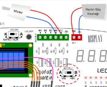
If you pulled the red circle enclosed in Part B of 5V gives the test kit. Your engine as shown in the picture if you connect 5V sent M4 5V is applied to the upper M4 motoro of the portion to which the one leg to GND new engine the other end VCC ie + 5V to operate the .arduino output with an external power supply, if any was taken to the part will start.
The Arduino code CIRCUIT:
#include<LiquidCrystal.h>LiquidCrystal LCD(11,10,2,3,4,5);void setup() {// put your setup code here, to run once:Serial.begin(9600);pinMode(8,OUTPUT);LCD.begin(16, 2);}void loop() {// put your main code here, to run repeatedly:float temperature = ((float)analogRead(A0) * 5.0 / 1024.0) - 0.5;temperature = temperature / 0.01;LCD.setCursor(0,1);LCD.print(" ");LCD.print("SICAKLIK:");LCD.print(temperature);LCD.setCursor(0,1);if(temperature>30){digitalWrite(8, HIGH);}if(temperature<30){digitalWrite(8, LOW);}}


