

LDR LED Control
Introduction
this article dnyarduino located on LEDs and set in from the LDR light sensor with
on a project in we Realized.sens their experiments and projects that shape the LED detects light in the environment are among the most commonly used material. LDR, resistance incumbent upon by the light of the violence in the media value is the simplest kind of optical sensor can be set to reverse proportion. I have it in my project using the LDR light sensor on dnyarduıno according to the ambient light LEDs checks edeceğim.ışık than the LEDs serially When the flashing light reduced begins to fall speed of the LEDs.
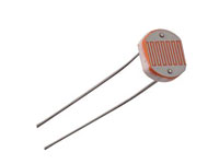
Photo resistor (LDR) light sensor
A photoresistor or light-dependent resistor (LDR) or photocell is a light-controlled variable resistor. The resistance of a photo resistor decreases with increasing incident light intensity; in other words, it exhibits photo conductivity. A photo resistor can be applied in light-sensitive detector circuits, and light- and dark-activated switching circuits.
A photoelectric device can be either intrinsic or extrinsic. An intrinsic semiconductor has its own charge carriers and is not an efficient semiconductor, for example, silicon. In intrinsic devices the only available electrons are in the valence band, and hence the photon must have enough energy to excite the electron across the entire bandgap. Extrinsic devices have impurities, also called dopants, added whose ground state energy is closer to the conduction band; since the electrons do not have as far to jump, lower energy photons (that is, longer wavelengths and lower frequencies) are sufficient to trigger the device. If a sample of silicon has some of its atoms replaced by phosphorus atoms (impurities), there will be extra electrons available for conduction. This is an example of an extrinsic semiconductor.
8 LEDs on the World
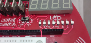
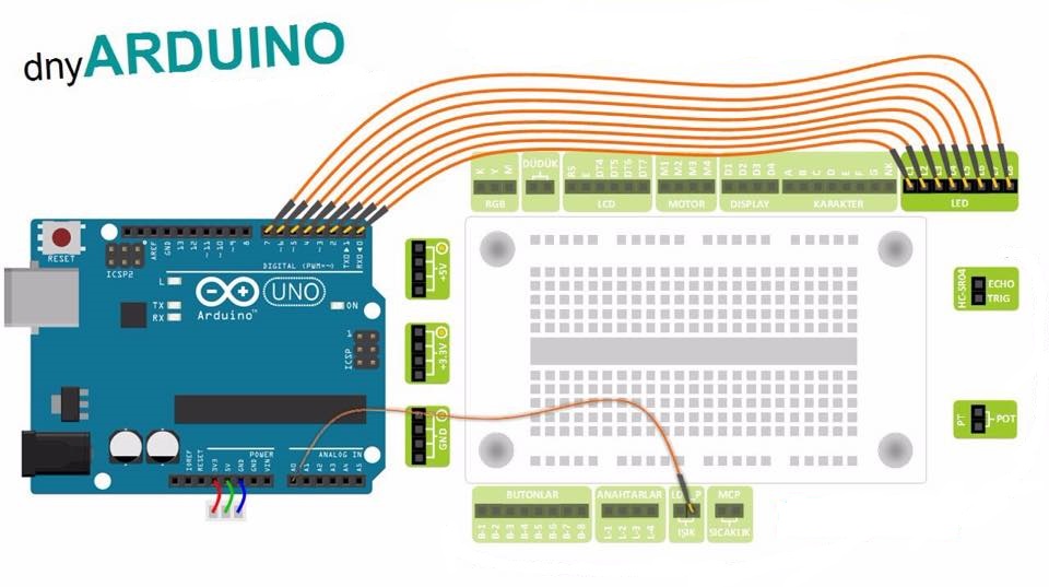
Photo of the circuit
Arduino code of the circuit
const int ledPin = 7;const int ledPin2 = 6;const int ledPin3 = 5;const int ledPin4 = 4;const int ledPin5 = 3;const int ledPin6 = 2;const int ledPin7 = 1;const int ledPin8 = 0;const int sensorPin = 0 ;void setup(){pinMode(ledPin,OUTPUT);pinMode(ledPin2,OUTPUT);pinMode(ledPin3,OUTPUT);pinMode(ledPin4,OUTPUT);pinMode(ledPin5,OUTPUT);pinMode(ledPin6,OUTPUT);pinMode(ledPin7,OUTPUT);pinMode(ledPin8,OUTPUT);}void loop(){int blinkRate = analogRead(sensorPin);digitalWrite(ledPin,HIGH);digitalWrite(ledPin2,HIGH);digitalWrite(ledPin3,HIGH);digitalWrite(ledPin4,HIGH);digitalWrite(ledPin5,HIGH);digitalWrite(ledPin6,HIGH);digitalWrite(ledPin7,HIGH);digitalWrite(ledPin8,HIGH);delay(blinkRate*2);digitalWrite(ledPin,LOW);digitalWrite(ledPin2,LOW);digitalWrite(ledPin3,LOW);digitalWrite(ledPin4,LOW);digitalWrite(ledPin5,LOW);digitalWrite(ledPin6,LOW);digitalWrite(ledPin7,LOW);digitalWrite(ledPin8,LOW);delay(blinkRate*2);}


