

Embedded System
Instructional Objectives
After going through this lesson the student would be able to
- Know what an embedded system is
- distinguish a Real Time Embedded System from other systems
- tell the difference between real and non-real time
- Learn more about a mobile phone
- Know the architecture
- Tell the major components of an Embedded system
Pre-Requisite
Digital Electronics, Microprocessors
Introduction
In the day-to-day life we come across a wide variety of consumer electronic products. We are habituated to use them easily and flawlessly to our advantage. Common examples are TV Remote Controllers, Mobile Phones, FAX machines, Xerox machines etc.
However, we seldom ponder over the technology behind each of them. Each of these devices does have one or more programmable devices waiting to interact with the environment as effectively as possible. These are a class of “embedded systems” and they provide service in real time. i.e. we need not have to wait too long for the action.
Let us see how an embedded system is characterized and how complex it could be? Take example of a mobile telephone: (Fig. 1.1)
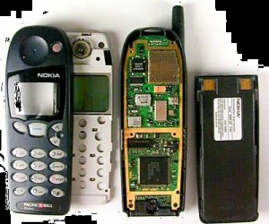
Fig. 1.1 Mobile Phones
When we want to purchase any of them what do we look for?
Let us see what are the choices available?
| Phone | Weight | Screen | Games | Camera | Radio | Ring tones | Memory |
| Price | / Size | ||||||
| Phone 1 | 88.1 x | TFT1 | Stauntman2 | Yes | No | Polyphonic | |
| Rs | 47.6 x | 65k | & | 4 x Zoom | |||
| 5000/- | 23.6 mm | Color | Monopoly3 | ||||
| 116 g | 96×32 | included | |||||
| screen | more | ||||||
| downloadable | |||||||
| Phone 2 | 89 x 49 | TFT | J2ME | Integrated | No | Polyphonic | |
| Rs | x 24.8 | 65k | Games: | Digital | and MP3 | ||
| 6000/- | mm | Color | Stauntman | Camera | |||
| 123 g | 176×220 | and | 1 M Pixel | ||||
| screen | Monopoly | ||||||
| More | |||||||
| downloadable | |||||||
| Phone 3 | 133.7 x | 176 x | Symbian and | No | FM | 3.4 MB | |
| Rs | 69.7 x | 208 | Java | Stereo | user | ||
| 5000/- | 20.2mm | pixel | download | memory | |||
| 137g | backlit | games or | built in. | ||||
| screen | packaged on | ||||||
| with | MMC cards | ||||||
| 4096 | |||||||
| colors |
Besides the above tabulated facts about the mobile handset, being a student of technology you may also like to know the following
Network type GSM2 or CDMA3 (Bandwidth),
Battery: Type and ampere hour Talk-time per one charge, Standby time
- Short for thin film transistor, a type of LCD flat-panel display screen, in which each pixel is controlled by from one to four transistors. The TFT technology provides better resolution of all the flat-panel techniques, but it is also the most expensive. TFT screens are sometimes called active-matrix LCDs.
- short form of Global System for Mobile Communications, one of the leading digital cellular systems. GSM uses narrowband Time Division Multiple Access (TDMA), which allows eight simultaneous calls on the same radio frequency. GSM was first introduced in 1991. As of the end of 1997, GSM service was available in more than 100 countries and has become the de facto standard in Europe and Asia.
- Short form of Code-Division Multiple Access, a digital cellular technology that uses spread-spectrum Unlike competing systems, such as GSM, that use TDMA, CDMA does not assign a specific frequency to each user. Instead, every channel uses the full available spectrum. Individual conversations are encoded with a pseudo-random digital sequence. CDMA is a military technology first used during World War II by the English allies to foil German attempts at jamming transmissions. The allies decided to transmit over several frequencies, instead of one, making it difficult for the Germans to pick up the complete signal.
From the above specifications it is clear that a mobile phone is a very complex device which houses a number of miniature gadgets functioning coherently on a single device.
Moreover each of these embedded gadgets such as digital camera or an FM radio along with the telephone has a number of operating modes such as:
- you may like to adjust the zoom of the digital camera,
- you may like to reduce the screen brightness,
- you may like to change the ring tone,
- you may like to relay a specific song from your favorite FM station to your friend using your mobile
- You may like to use it as a calculator, address book, emailing device etc.
These variations in the functionality can only be achieved by a very flexible device.
This flexible device sitting at the heart of the circuits is none other than a Customized Microprocessor better known as an Embedded Processor and the mobile phone housing a number of functionalities is known as an Embedded System.
Since it satisfies the requirement of a number of users at the same time (you and your friend, you and the radio station, you and the telephone network etc) it is working within a time-constraint, i.e. it has to satisfy everyone with the minimum acceptable delay. We call this as to work in “Real Time”. This is unlike your holidaying attitude when you take the clock on your stride.
We can also say that it does not make us wait long for taking our words and relaying them as well as receiving them, unlike an email server, which might take days to receive/deliver your message when the network is congested or slow.
Thus we can name the mobile telephone as a “Real Time Embedded System” (RTES)
Definitions
Now we are ready to take some definitions
Real Time
“‘Real’-time usually means time as prescribed by external sources”
For example the time struck by clock (however fast or late it might be) . The timings generated by your requirements. You may like to call someone at mid-night and send him a picture. This external timing requirements imposed by the user is the real-time for the embedded system.
Embedded (Embodiment)
“Embodied phenomena are those that by their very nature occur in real time and real space” In other words, A number of systems coexist to discharge a specific function in real time
Thus “A Real Time Embedded System” (RTES) is precisely the union of subsystems to discharge a specific task coherently. Hence forth we call them as RTES. RTES as a generic term may mean a wide variety of systems in the real world. However we will be concerned about them which use programmable devices such as microprocessors or microcontrollers and have specific functions. We shall characterize them as follows.
Characteristics of an Rtes
Single-Functioned
Here “single-functioned” means specific functions. The RTES is usually meant for very specific functions. Generally a special purpose microprocessor executes a program over and over again for a specific purpose. If the user wants to change the functionality, e.g. changing the mobile phone from conversation to camera mode or calculator mode the program gets flushed out and a new program is loaded which carries out the requisite function. These operations are monitored and controlled by an operating system called as Real Time Operating System (RTOS) which has much simpler complexity but more rigid constraints as compared to the conventional operating systems such as Micro Soft Windows and Unix etc.
Tightly Constrained
The constraints on the design and marketability of RTES are more rigid than their non-real-time non-embedded counter parts. Time-domain constraints are the first thing that is taken care while developing such a system. Size, weight, power consumption and cost4 are the other major factors.
Reactive and Real Time
Many embedded systems must continually react to changes in the system’s environment and must compute certain results in real time without delay. For example, a car’s cruise controller continually monitors and reacts to speed and brake sensors. It must compute acceleration or deceleration amounts repeatedly within a limited time; a delayed computation could result in a failure to maintain control of the car. In contrast a desktop computer system typically focuses on computations, with relatively infrequent (from the computer’s perspective) reactions to input devices. In addition, a delay in those computations, while perhaps inconvenient to the computer user, typically does not result in a system failure.
4 Very few in India will be interested to buy a mobile phone if it costs Rs50,000/- even if it provides you a faster processor with 200MB of memory to store your address, your favorite mp3 music and plays them , acts as a small-screen TV whenever you desire, takes your call intelligently
However in USA majority can afford it !!!!!!
Common Architecture of Real Time Embedded Systems
Unlike general purpose computers a generic architecture can not be defined for a Real Time Embedded Systems. There are as many architecture as the number of manufacturers. Generalizing them would severely dilute the soul purpose of embodiment and specialization.
However for the sake of our understanding we can discuss some common form of systems at the block diagram level. Any system can hierarchically divided into subsystems. Each sub-system may be further segregated into smaller systems. And each of these smaller systems may consist of some discrete parts. This is called Hardware configuration.
Some of these parts may be programmable and therefore must have some place to keep these programs. In RTES the on- chip or on- board non-volatile memory does keep these programs. These programs are the part of the Real Time Operating System (RTOS) and continually run as long as the gadget is receiving power. A part of the RTOS also executes itself in the stand -by mode while taking a very little power from the battery. This is also called the sleep mode of the system.
Both the hardware and software coexist in a coherent manner. Tasks which can be both carried out by software and hardware affect the design process of the system. For example a multiplication action may be done by hardware or it can be done by software by repeated additions. Hardware based multiplication improves the speed at the cost of increased complexity of the arithmetic logic unit (ALU) of the embedded processor. On the other hand software based multiplication is slower but the ALU is simpler to design. These are some of the conflicting requirements which need to be resolved on the requirements as imposed by the overall system. This is known as Hardware-Software Codesign or simply Codesign.
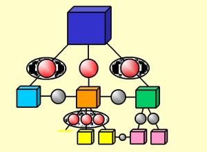
Fig. 1.2 The System Interface and Architecture
The red and grey spheres in Fig.1.2 represent interface standards. When a system is assembled it starts with some chassis or a single subsystem. Subsequently subsystems are added onto it to make it a complete system.
Let us take the example of a Desktop Computer. Though not an Embedded System it can give us a nice example of assembling a system from its subsystems.
You can start assembling a desktop computer (Fig.1.3) starting with the chassis and then take the SMPS (switched mode power supply), motherboard, followed by hard disk drive, CDROM drive, Graphic Cards, Ethernet Cards etc. Each of these subsystems consists of several components e.g. Application Specific Integrated Circuits (ASICs), microprocessors, Analog as well as Digital VLSI circuits, Miniature Motor and its control electronics, Multilevel Power supply units crystal clock generators, Surface mounted capacitors and resistors etc. In the end you close the chassis and connect Keyboard, Mouse, Speakers, Visual Display Units, Ethernet Cable, Microphone, Camera etc fitting them into certain well-defined sockets.
As we can see that each of the subsystems inside or outside the Desktop has cables fitting well into the slots meant for them. These cables and slots are uniform for almost any Desktop you choose to assemble. The connection of one subsystem into the other and vice-versa is known as Interfacing. It is so easy to assemble because they are all standardized. Therefore, standardization of the interfaces is most essential for the universal applicability of the system and its compatibility with other systems. There can be open standards which makes it exchange information with products from other companies. It may have certain key standards, which is only meant for the specific company which manufactures them.
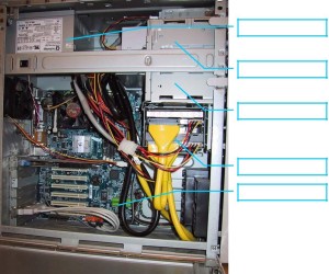
Fig. 1.3 Inside Desktop Computer
A Desktop Computer will have more open standards than an Embedded System. This is because of the level of integration in the later. Many of the components of the embedded systems are integrated on to a single chip. This concept is known as System on Chip (SOC) design. Thus there are only few subsystems left to be connected.
Analyzing the assembling process of a Desktop let us comparatively assess the possible subsystems of the typical RTES.
One such segregation is shown in Fig.1.4. The explanation of various parts as follows:
User Interface: for interacting with users. May consists of keyboard, touch pad etc
ASIC: Application Specific Integrated Circuit: for specific functions like motor control, data modulation etc.
Microcontroller(µC): A family of microprocessors
Real Time Operating System (RTOS): contains all the software for the system control and user interface
Controller Process: The overall control algorithm for the external process. It also provides timing and control for the various units inside the embedded system.
Digital Signal Processor (DSP) a typical family of microprocessors DSP assembly code: code for DSP stored in program memory
Dual Ported Memory: Data Memory accessible by two processors at the same time CODEC: Compressor/Decompressor of the data
User Interface Process: The part of the RTOS that runs the software for User Interface activities
Controller Process: The part of the RTOS that runs the software for Timing and Control amongst the various units of the embedded system
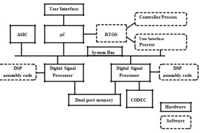
Fig. 1.4 Architecture of an Embedded System
The above architecture represents a hypothetical Embedded System (we will see more realistic ones in subsequent examples). More than one microprocessor (2 DSPs and 1 µC) are employed here to carry out different tasks. As we will learn later, the µC is generally meant for simpler and slower jobs such as carrying out a Proportional Integral (PI) control action or interpreting the user commands etc. The DSP is a more heavy duty processor capable of doing real time signal processing and control. Both the DSPs along with their operating systems and codes are independent of each other. They share the same memory without interfering with each other. This kind of memory is known as dual ported memory or two-way post-box memory. The Real Time Operating System (RTOS) controls the timing requirement of all the devices. It executes the over all control algorithm of the process while diverting more complex tasks to the DSPs. It also specifically controls the µC for the necessary user interactivity. The ASICs are specialized units capable of specialized functions such as motor control, voice encoding, modulation/demodulation (MODEM) action etc. They can be digital, analog or mixed signal VLSI circuits. CODECs are generally used for interfacing low power serial Analog-to-Digital Converters (ADCs). The analog signals from the controlled process can be monitored through an ADC interfaced through this CODEC.
If you have any question than you can ask it to every readers by clicking below link


