
LED dot matrix display:
An LED dot matrix display consists of a matrix of LED’s arranged in a rectangular configuration. The desired character or graphics can be displayed by switching ON /OFF a desired configuration of LED’s. Common display configurations available are 7×5, 8×8, 7×15, etc. LED dot matrix can be used in simple display applications where the resolution is not a big concern. The figure below shows the arrangement of LEDs in a typical 7×5 dot matrix display.
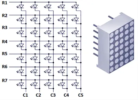
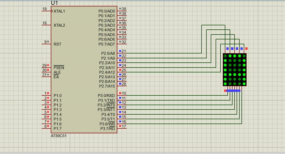
In the above diagram you can see that only one LED in a row will be ON at a time but any number of LEDs in a column can be ON at a time. That means the microcontroller’s port pin can directly drive a row but it requires additional circuit for driving the column lines. The circuit diagram for interfacing dot matrix display and 8051 microcontroller is shown below.
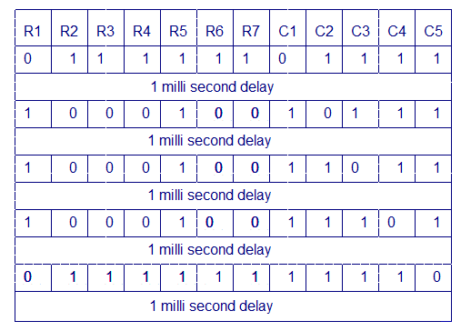
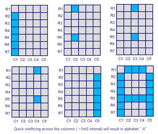
 Display ‘A’ on 5×7 LED Dot Matrix
Keil C Program:
#include<reg51.h>
unsigned int Col[5]= {0xfe,0xfd,0xfb,0xf7,0xef};
unsigned int Row[5]={0xfe,0x11,0x11,0x11,0xfe};
void delay (unsigned int x)
{
unsigned int k,m;
for (k = 0;k<x;k++)
{
for(m=0;m<500;m++);
}
}
void main()
{
unsigned int d;
while(1)
{
for(d=0;d<5;d++)
{
P2=Col[d];
P3=Row[d];
delay(1);
}
}
}


