

Interfacing LCD with LPC 2148
[nextpage title=”Summary” ]LCD stands for Liquid Crystal Display used to display numbers, strings and special characters as per the application. It is one of the widely used modules in embedded system. Almost all embedded product requires LCD.
Advantage of LCD over LEDs is its ability to display any number, alphabet, special characters and user defined symbol (at extra effort for programming) without increasing number of pins required to be connected with controller.Interfacing of LCD with LPC2148 differs little bit compared to interfacing with 8051 or AVR which operates on 5V. LCD operates on 5V but LPC 2148 operates on 3.3V so we have to take care of this fact for the controller pins which has to be connected with LCD.
This requires level shifter circuit to be interfaced. The entire article aims to cover basics of LCD and level shifter circuit designing with programming to interface LCD with LPC 2148.
[/nextpage][nextpage title=”Description” ]Let us start with basics of LCD. JHD 162A 16×2 LCD is widely used and easily available in market. It has total 16 pins which can be divided into three categories.
1. Power Control pins: 1,2,3,15,16
2. Control Pins: 4,5,6
3. Data Pins: 7 to 14
Functions of pins are as follows.
| Pin number | Pin Name | Function |
| 1 | Gnd | Ground pin |
| 2 | Vcc | Supply for LCD (4.7-5.3V) |
| 3 | Vee | Contrast Control |
| 4 | RS | Register select0-Command Register1-Data Register |
| 5 | R/W | Read/Write0-Write LCD1-Read LCD |
| 6 | E | Enable pin |
| 7-14 | DB0-DB7 | Data pins |
| 15 | V+ | Supply for backlight |
| 16 | Gnd | Ground pin of backlight supply |
LCD needs to be configured properly. To configure LCD, we must know the command structure which is as given below.
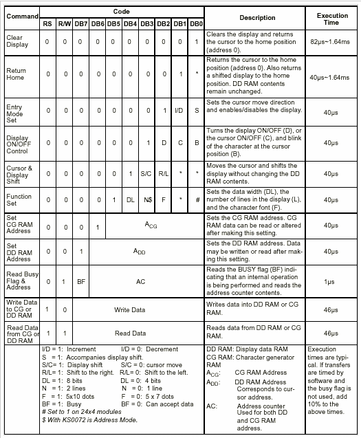
This table must be understood properly for programming.
Well to reduce your efforts, generally required commands are short listed here.
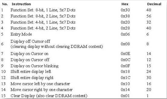
Once you are aware of command structure, let’s move ahead.
LCD can operate in two modes.
1. Command Mode: In this mode, RS pin is at logic 0 and the data on pin 7-14 represents the command which specifies the actions to be performed like clear LCD, go to home position, blink cursor etc.
2. Data Mode: In this mode, RS pin is at logic 1 and data op pin 7-14 represents the data to be displayed on LCD.
While operating in data mode, we must keep in mind that the pattern to be displayed on dot matrix is already stored in internal memory of LCD. It is given below.
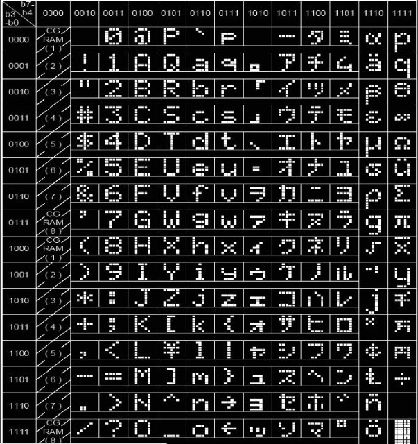
So to display any character on LCD, we must provide ASCII value of that on data pins and LCD is smart enough to do the rest. To convert
any number into ASCII, we must add 48 decimal value to it. So ASCII of 0 is 48, of 1 is 49 etc.
How many pins LCD needs ??
As provided earlier, LCD has 8 data pins and 3 control pins. So it needs 11 pins of controller for operation. But by smart thinking, we can reduce it to six. Let’s see how we can do that.
RW pin is for specifying read or write operation. Well if LCD is output device so where we have to read it ? Let’s understand this properly.
LCD is slow compared to Microc-controllers and it needs time to perform the operations. Assume that controller is asking LCD to print data continuously. When LCD will receive command for that, it will start displaying on LCD but if controller will send another data and if LCD has not finished the task of displaying first data, the later data will be lost and will not be displayed on it.
To avoid this, LCD has one method known as busy flag. In this, MSB of data pins ie. Pin 14 is used as busy flag. Once LCD will start performing and actions, it will raise pin 14 high to indicate that it is in busy state. Once the operation is completed, it will bring it down. Controller must check the status of pin 14 before sending further data or command to avoid any loss of data.
Here it is necessary to read pin 14 and RW has to be made high to read. We can save 1 controller pin here. Although LCD is slow, it is able to finish executaion of command within few machine cycles. So after giving any command or data, if we provide delay of few microseconds, LCD will finish its task within that much time. So we don’t have to read status of pin14 and we can permenately ground it and save controller pin.
Another beautiful option available is to use LCD in 4bit mode. Here the data will be sent in two nibbles instead of a complete byte at a time. In this, only higher nibble of data pins has been connected with controller and pinf 7-10 of LCD are in NC state.
In this way, we need only 6 pins (4 bit data bus, RS and E) are required for LCD interafcing.
Circuit Diagram
Once you are clear with basics of LCD, command structure and basic commands, let’s move ahead with hardware connections.
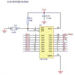
As mentioned earlier, LPC 2148 operates on 3.3V while LCD requires 5V for operation as well as 5V signals on data and control pins. So we need level shifter in between LCD and LPC 2148.
Some of the buffers / level shifters than can be used are : SN74AHC244N , SN74AC241N , CD74AC244E , CD4050B , etc.. out of which CD74AC244E is readily available. The below circuit explains how we can interface LCD with LPC 2148.
[/nextpage][nextpage title="Code" ]/* Functions for LCD are as follows.
Function Name |
Description |
void Delay(unsigned long b); |
Provide delay of few microseconds |
void write_command(int cmd); |
Give command to LCD |
void write_data(int dat); |
Display data on LCD |
void init_lcd(void); |
Initialize LCD |
void printlcd(char *CPtr); |
Display string on LCD |
We have declared thess functions in LCD4BIT.C files and defined in LCD4BIT.H file using moddular programming approach.

Once above files are created, we can use code to display data on LCD.

 Program for LCD.h file  */

#include <LPC21xx.h>
void Delay(unsigned long b)
{
  while (--b!=0);
}
void write_command(int cmd)
 {
  IO1CLR  |= 0x00f00000;                    // Clear Data pins
  IO1CLR  |= 0x00040000;                            // RW = 0
  IO1CLR  |= 0X00020000;                            // RS= 0,
  IO1SET  |= 0x00f00000 & cmd;           //Set Data pins
  IO1SET  |= 0X00080000;                            // Enable = 1
  Delay(30000);                                   // Provide Delay
  IO1CLR  |= 0x00080000;                    // Set Enable=0
  }
void write_data(int dat)
{
  IO1CLR  |= 0x00f00000;                    // Clear Data pins4-D7
  IO1CLR  |= 0x00040000;                   // RW= 0
  IO1SET  |= 0X00020000;                    //RS= 1
  IO1SET  |= 0x00f00000 & dat;            // Set Data pins
  IO1SET  |= 0X00080000;                    // Enable = 1
  Delay(30000);                                   //Provide Delay
  IO1CLR  |= 0x00080000;                    //Set Enable=0
  }
void lcd_data(char dat)
{
  write_data(dat << 16);
  write_data(dat << 20);
}
void lcd_command(char cmd)
{
  write_command(cmd << 16);
  write_command(cmd << 20);
}
void printlcd(char *CPtr)
{
  while(*CPtr != '\0')
 {
  lcd_data(*CPtr);
  CPtr++;
  Delay(20000);
 }
}
void init_lcd(void)
 {
  IO1DIR    |= 0x00FE0000;
  Delay(200000) ;
  Delay(100000);
  write_command(0x30 << 16);
  Delay(100000);
  write_command(0x20 << 16);
  lcd_command(0x01);                          /* clear display */
  lcd_command(0x06);                          /* auto address inc */
  lcd_command(0x0c);                          /* cursor off */
  lcd_command(0x80);                          /* first location */
  }
[/nextpage][nextpage title="Code2" ]//Program for main application
#include <LPC21xx.h>
#include "lcd4bit.h"
int main(void) {
  init_lcd();
  while(1)
        {
        lcd_command(0x01);
        lcd_command(0x80);
        printlcd("Welcome To");
  lcd_command(0xC0);
  printlcd("EngineersGarage");
        Delay(50000000);
        lcd_command(0x01);
        lcd_command(0x80);
        printlcd("LCD Interface ");
  lcd_command(0xC0);
  printlcd("with LPC 2148");
        Delay(50000000);
        lcd_command(0x01);
        lcd_command(0x80);
        printlcd("Developed By:");
  lcd_command(0xC0);
  printlcd("Dishant Shah");
        Delay(50000000);
        }
  }[/nextpage]


