
Interfacing DS1307 with Atmega 16 AVR MCU
[nextpage title=”Description”
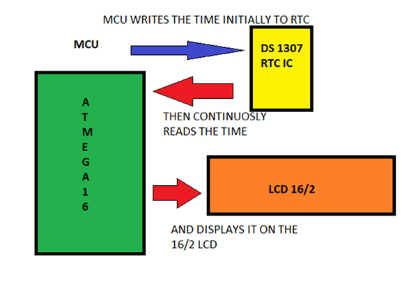
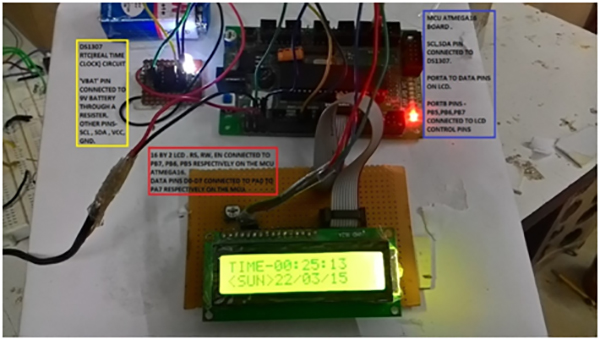
Working of the Circuit
In this project mcu atmega16 communicate with DS1307 IC on I2C communication protocol, in which MCU works as master and DS1307 as a slave.I2C communication takes place through SDA(serial data) and SCL(serial clock line). Atmega16 and DS1307 are connected through SCL SDA lines. Atmega16 writes the data In registers of DS1307 and then reads its reads it.The data read by MCU is displayed on the LCD.
Circuit Description
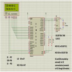
The circuit consists of Atmega16 MCU, DS1307 IC and 16/2 LCD. The microcontroller Atmega16 communicates to the DS1307 through the I2C serial data bus line SDA and serial clock line SCL.
The PC0 and PC1 pins of microcontroller apart from I/O operations also performs SCL and SDA functions respectively.
During I2C operations the SCL and SDA lines are pulled high externally (refer the circuit diagram). External pull up means connecting the line to VCC through a resister .The value of resister I have used is 10k ohm. 4.7k ohm or 5.6k ohm can also be used.
The LCD is connected to PORTA and PORTB of the Atmega16. The data pins D0 to D7 are connected to respective pins A0 to A7 of the Atmega16.The control pins RS, R/W and EN are connected to PB7,PB6,PB5 pins of Atmega16 respectively.
ATmega16 is an 8-bit high performance microcontroller of Atmel’s Mega AVR family with low power consumption. Atmega16 is based on enhanced RISC (Reduced Instruction Set Computing, Know more about RISC and CISC Architecture) architecture with 131 powerful instructions. Most of the instructions execute in one machine cycle. Atmega16 can work on a maximum frequency of 16MHz.
ATmega16 has 16 KB programmable flash memory, static RAM of 1 KB and EEPROM of 512 Bytes. The endurance cycle of flash memory and EEPROM is 10,000 and 100,000, respectively.
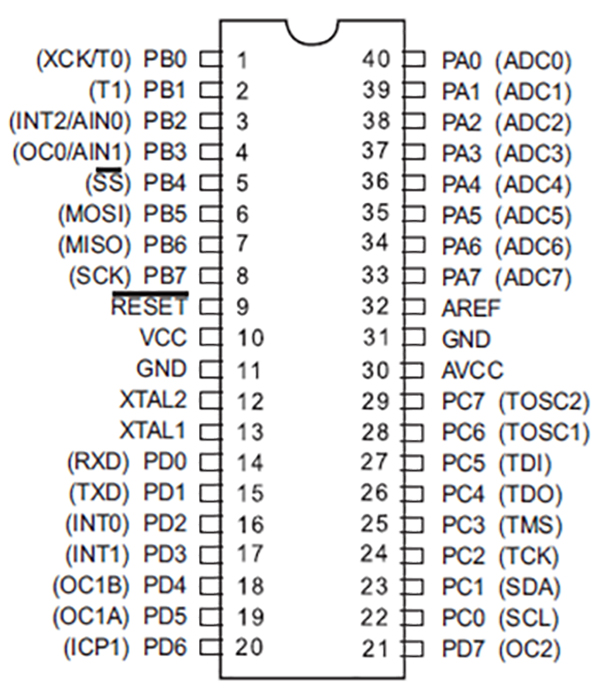
ATmega16 is a 40 pin microcontroller. There are 32 I/O (input/output) lines which are divided into four 8-bit ports designated as PORTA, PORTB, PORTC and PORTD.
ATmega16 has various in-built peripherals like USART, ADC, Analog Comparator, SPI, JTAG etc. Each I/O pin has an alternative task related to in-built peripherals. The following table shows the pin description of ATmega16.
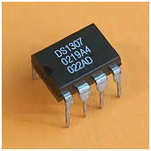
-VBAT is to be supplied 3V through a 3V lithium cell.
-Crystal value used is 32.768kHz, it is connected to X1 and X2.
I2C COMMUNICATION
I²C (Inter-Integrated Circuit), pronounced I-squared-C, is a multi-master, multi-slave, single-ended, serial computer bus invented by Philips Semiconductor, known today as NXP Semiconductors, used for attaching low-speed peripherals to computermotherboards and embedded systems. Alternatively I²C is spelled I2C (pronounced I-two-C) or IIC (pronounced I-I-C)
I²C uses only two bidirectional open-drain lines, Serial Data Line (SDA) and Serial Clock Line (SCL), pulled up withresistors. Typical voltages used are +5 V or +3.3 V although systems with other voltages are permitted.
The I²C reference design has a 7-bit or a 10-bit (depending on the device used) address space.[3] Common I²C bus speeds are the 100 kbit/s standard mode and the 10 kbit/s low-speed mode, but arbitrarily low clock frequencies are also allowed. Recent revisions of I²C can host more nodes and run at faster speeds (400 kbit/s Fast mode
Note the bit rates are quoted for the transactions between master and slave without clock stretching or other hardware overhead. Protocol overheads include a slave address and perhaps a register address within the slave device as well as per-byte ACK/NACK bits. Thus the actual transfer rate of user data is lower than those peak bit rates alone would imply. For example, if each interaction with a slave inefficiently allows only 1 byte of data to be transferred, the data rate will be less than half the peak bit rate.
The maximum number of nodes is limited by the address space, and also by the total bus capacitance of 400 pF, which restricts practical communication distances to a few meters.
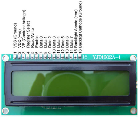
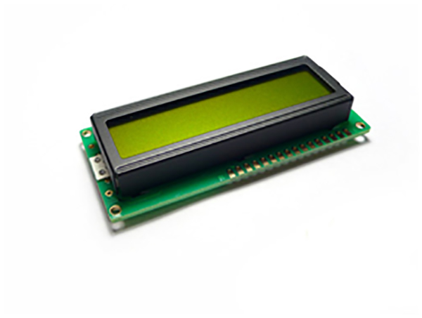
16 BY 2 LCD –YJD1602A1
The LCD receives the data from Atmega16 and displays it in readable format. Pin1 VSS is connected to GND, Pin2 VCC connected to 5V and Pin3 VE is connected to a potentiometer to receive a contrast voltage b/w 0 and 5V.
RS, R/W,EN are connected to PB7,PB6,PB5 pins on the MCU and 8 data pins are connected to PORTA of MCU.
[nextpage title=”Code”
#include <avr/io.h>
#include <util/delay.h>
#include <avr/interrupt.h>
#include <stdlib.h>
#define MT_SLA_ACK1 0x18 //twi interface commands for ds1307
#define MT_DATA_ACK1 0x28
#define START 0x08
#define MT_SLA_ACK 0x40
#define MT_DATA_ACK 0x58
#define SLA_R 0b11010001 //address for ds1307
#define SLA_W 0b11010000
uint8_tBCDToDecimal (uint8_t bcdByte)
{
return (((bcdByte& 0xF0) >> 4) * 10) + (bcdByte& 0x0F);
}
uint8_tDecimalToBCD (uint8_t decimalByte)
{
return (((decimalByte / 10) << 4) | (decimalByte % 10));
}
uint8_t address;
voidinitialize_LCD(void);
charfirst_column_positions_for_LCD[4]={0,64,20,84};
voidcheck_if_LCDisbusy(void); // checking LCD ready to process
voidLCD_enabledisplay(void); //disply enable
voidsend_A_command(unsigned char command); // sending command
voidsend_A_character(unsigned char character); // sending character
voidsend_A_string(char *stringsofcharacter); // send string
voidgoto_location(uint8_t x, uint8_t y);
voidsend_string_and_location(uint8_t x,uint8_t y, char *stringOFcharacter);
voidsend_integer(uint8_t x,uint8_t y,intintegertodisplay,charnumberdigits);
uint8_t data_Read;
uint8_t H,M,S,WK,DY,MN,YR;
uint8_t H1,M1,S1,WK1,DY1,MN1,YR1;
voidTWI_bit_rate_set(void)
{
TWBR=8; // set SCL frequency to 400kHz
TWCR|=1<<TWEN;
}
intTWI_start()
{
TWCR = (1<<TWINT)|(1<<TWSTA)|(1<<TWEN); // set start
while (!(TWCR & (1<<TWINT))); //Wait for TWINT Flag set. This indicates that the START condition has been transmitted
if ((TWSR & 0xF8) != START) //Check value of TWI Status Register. Mask prescaler bits. If status different from START go to ERROR
return 0;
}
intTWI_send_address_read() // READ……….send slave address in read mode
{
TWDR = SLA_R;
TWCR = (1<<TWINT) | (1<<TWEN); // Load SLA_W into TWDR Register. Clear TWINT bit in TWCR to start transmission of address
while (!(TWCR & (1<<TWINT))); //Wait for TWINT Flag set. This indicates that the SLA+W has been transmitted, and ACK/NACK has been received
if ((TWSR & 0xF8) != MT_SLA_ACK) // Check value of TWI Status Register. Mask prescaler bits. If status different from MT_SLA_ACK go to ERROR
return 0;
}
intTWI_send_addr_data(uint8_t data) // WRITE………send the address of data
{
TWDR=data;
TWCR = (1<<TWINT) | (1<<TWEN); //Load DATA into TWDR Register. Clear TWINT bit in TWCR to start transmission of data
while (!(TWCR & (1<<TWINT))); // Wait for TWINT Flag set. This indicates that the DATA has been transmitted, and ACK/NACK has been received
if ((TWSR & 0xF8) != MT_DATA_ACK1) // Check value of TWI Status Register. Mask prescaler bits. If status different from MT_DATA_ACK go to ERROR
return 0;
}
intTWI_get_data() // READ…..get the address of the data required
{
TWCR = (1<<TWINT) | (1<<TWEN); //Load DATA into TWDR Register. Clear TWINT bit in TWCR to start transmission of data
while (!(TWCR & (1<<TWINT))); // Wait for TWINT Flag set. This indicates that the DATA has been transmitted, and ACK/NACK has been received
data_Read=TWDR;
TWCR = (1<<TWINT) | (1<<TWEN); //Load DATA into TWDR Register. Clear TWINT bit in TWCR to start transmission of data
while (!(TWCR & (1<<TWINT))); // Wait for TWINT Flag set. This indicates that the DATA has been transmitted, and ACK/NACK has been received
if ((TWSR & 0xF8) != MT_DATA_ACK) // Check value of TWI Status Register. Mask prescaler bits. If status different from MT_DATA_ACK go to ERROR
return 0;
}
intTWI_send_address_write() // WRITE……..send slave address in write mode
{
TWDR = SLA_W;
TWCR = (1<<TWINT) | (1<<TWEN); // Load SLA_W into TWDR Register. Clear TWINT bit in TWCR to start transmission of address
while (!(TWCR & (1<<TWINT))); //Wait for TWINT Flag set. This indicates that the SLA+W has been transmitted, and ACK/NACK has been received
if ((TWSR & 0xF8) != MT_SLA_ACK1) // Check value of TWI Status Register. Mask prescaler bits. If status different from MT_SLA_ACK go to ERROR
return 0;
}
voidTWI_stop() //…………………………..stop…………………………………………//
{
TWCR = (1<<TWINT)|(1<<TWEN)|(1<<TWSTO); // Transmit STOP condition
}
int write(uint8_t pg_addr,uint8_t data1)
{
TWI_bit_rate_set();
TWI_start();
TWI_send_address_write();
TWI_send_addr_data(pg_addr); // send address of page
TWI_send_addr_data(data1); // send data to be written to the address
TWI_stop();
}
int read(uint8_t pg_addr)
{
TWI_bit_rate_set();
TWI_start();
TWI_send_address_write();
TWI_send_addr_data(pg_addr);
TWI_start();
TWI_send_address_read();
TWI_get_data();
TWI_stop();
}
voiddisplay_num(uint8_t DIG,uint8_t loc)
{
if(DIG<=9)
{send_integer(loc,1,0,3);
send_integer((loc+1),1,DIG,3);
}
else
send_integer(loc,1,DIG,3);
}
voiddisplay_ALP(uint8_t DIG,uint8_t loc)
{
if(DIG<=9)
{send_integer(loc,2,0,3);
send_integer((loc+1),2,DIG,3);
}
else
send_integer(loc,2,DIG,3);
}
voiddisplay_weekday(uint8_t WK)
{
if(WK==1){send_string_and_location(1,2,”<SUN>”);}
else if(WK==2){send_string_and_location(1,2,”<MON>”);}
else if(WK==3){send_string_and_location(1,2,”<TUE>”);}
else if(WK==4){send_string_and_location(1,2,”<WED>”);}
else if(WK==5){send_string_and_location(1,2,”<THU>”);}
else if(WK==6){send_string_and_location(1,2,”<FRI>”);}
else if(WK==7){send_string_and_location(1,2,”<SAT>”);}
}
#define sec_register 0x00
#define min_register 0x01
#define hour_register 0x02
#define weekday_weekend_register 0x03
#define day_register 0x04
#define month_register 0x05
#define year_register 0x06
voidRTC_write_data(void)
{
write(sec_register,DecimalToBCD(00));
write(min_register,DecimalToBCD(52));
write(hour_register,DecimalToBCD(20));
write(weekday_weekend_register,DecimalToBCD(1));
write(day_register,DecimalToBCD(15));
write(month_register,DecimalToBCD(03));
write(year_register,DecimalToBCD(15));
}
voidRTC_read_data()
{
read(hour_register);
hour_digits(data_Read);
read(min_register);
min_digits(data_Read);
read(sec_register);
sec_digits(data_Read);
read(weekday_weekend_register);
weekday_weekend_digits(data_Read);
read(day_register);
day_digits(data_Read);
read(month_register);
month_digits(data_Read);
read(year_register);
year_digits(data_Read);
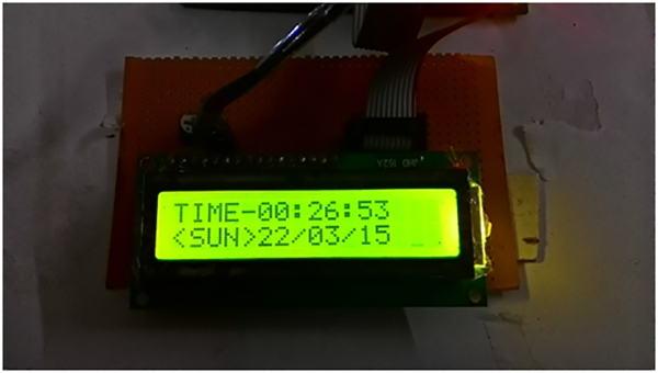
send_string_and_location(1,1,”TIME-“);
display_num(H,6);
send_string_and_location(8,1,”:”);
display_num(M,9);
send_string_and_location(11,1,”:”);
display_num(S,12);
display_weekday(WK);
display_ALP(DY,6);
send_string_and_location(8,2,”/”);
display_ALP(MN,9);
send_string_and_location(11,2,”/”);
display_ALP(YR,12);
}
voidhour_digits(uint8_t data)
{H=BCDToDecimal(data);}
voidsec_digits(uint8_t data)
{S=BCDToDecimal(data);}
voidmin_digits(uint8_t data)
{M=BCDToDecimal(data);}
voidweekday_weekend_digits(uint8_t data)
{WK=BCDToDecimal(data);}
voidday_digits(uint8_t data)
{DY=BCDToDecimal(data);}
voidmonth_digits(uint8_t data)
{MN=BCDToDecimal(data);}
voidyear_digits(uint8_t data)
{YR=BCDToDecimal(data);}
voidinitialize_LCD()
{
DDRB|=(1<<5)|(1<<6)|(1<<7);
_delay_ms(2);
send_A_character(0x01);
_delay_ms(2);
send_A_command(0x38);
_delay_us(10);
send_A_command(0b00001110);
_delay_us(10);
}
voidcheck_if_LCDisbusy()
{
DDRA=0;
PORTB|=1<<6;
PORTB&=~1<<6;
while(PORTA>=0x80)
{
LCD_enabledisplay();
}
DDRA=0xFF;
}
voidLCD_enabledisplay()
{
PORTB|=1<<5; // enable on , bit of delay then off
_delay_ms(5);
PORTB&=~1<<5;
}
voidsend_A_command(unsigned char command)
{
check_if_LCDisbusy();
PORTA=command;
PORTB&=~((1<<6)|(1<<7)); // readwrite =0 and register select also =0 for sending a command
LCD_enabledisplay();
PORTA=0;
}
voidsend_A_character(unsigned char character)
{
check_if_LCDisbusy(); // readwrite =0 and register select =1 for sending a command
PORTA=character;
PORTB&=~(1<<6);
PORTB|=1<<7;
LCD_enabledisplay();
DDRA=0;
}
voidsend_A_string(char *stringsofcharacter)
{
while(*stringsofcharacter>0)
{
send_A_character(*stringsofcharacter++);
}
}
voidgoto_location(uint8_t x, uint8_t y) // takes cursor to the desired position as on x and y value.
{
send_A_command(0x80 + first_column_positions_for_LCD[y-1]+ (x-1));
}
voidsend_string_and_location(uint8_t x,uint8_t y, char *stringofcharacters) // the string is taken to the desired location on lcd
{
goto_location(x,y);
send_A_string(stringofcharacters);
}
voidsend_integer(uint8_t x,uint8_t y,intintegertodisplay,charnumberdigits) // specify the no. of digits of the integer
{
charstringtodisplay[numberdigits];
itoa(integertodisplay,stringtodisplay,10); // 10 means decimal -user undersatandable
// converted the integer to string
inti;
for(i=0;i<4;i++) {send_A_string(” “);} //reserves 4 digits for our display and removes any garbage
send_string_and_location(x,y,stringtodisplay);
send_A_string(” “); // space provided to get rid of any garbage or 0 value
}
void wait(int a)
{ inti;
for(i=1;i<=a;i++)
{_delay_ms(1000);}
}
int main(void)
{
initialize_LCD();
send_A_command(0x01);
RTC_write_data();
// first program with write statement then comment write statement and reprogram
while(1)
{
RTC_read_data();
}
}[nextpage title=”Description” ]Please insert your text here![/nextpage]


