

[nextpage title=”SUMMARY” ]
SUMMARY:
Seven Segment displays are used in a number of systems to display the numeric information. The seven segment can display one digit at a time. Thus the no. of segments used depends on the no. of digits in the number to be displayed. Interfacing seven segment with a controller or MCU is tricky. This article explains the interfacing of seven segment with MCU AT89C51. It displays the digits 0 to 9 continuously at a predefined time delay.
[visitor]
[/visitor]
[/nextpage]
[nextpage title=”DESCRIPTION” ]
DESCRIPTION:
A seven segment consists of eight LEDs which are aligned in a manner so as to display digits from 0 to 9 when proper combination of LED is switched on. Seven segment uses seven LED’s to display digits from 0 to 9 and the eighth LED is used for the dot. A typical seven segment pinout looks like as shown in the figure below.
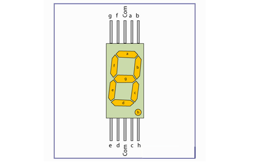
Seven Segment are available in two configuration – (1) Common Anode (2) Common Cathode.
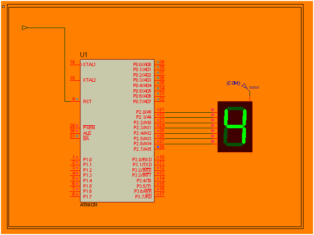
Here common anode seven segment display is used because the output current of the microcontroller is not sufficient enough to drive the LED’s, similar to the case of driving an LED. The circuit diagram shows the connections of seven segment to the controller. The pins a to g of the Seven Segment are connected to the Port P2 of the microcontroller. The common pin of the seven segment is connected to Vcc. The ‘h’ has not been used, which is the dot pin of the controller.
Since the seven segment display works on negative logic, we will have to provide logic 0 to the corresponding pin to make an LED glow. Table below shows the hex values used to display the different digits.
| DIGIT | a | b | c | d | e | f | g | HEX Value |
| 0 | 0 | 0 | 0 | 0 | 0 | 0 | 1 | 0x40 |
| 1 | 1 | 0 | 0 | 1 | 1 | 1 | 1 | 0xF9 |
| 2 | 0 | 0 | 1 | 0 | 0 | 1 | 0 | 0x24 |
| 3 | 0 | 0 | 0 | 0 | 1 | 1 | 0 | 0x30 |
| 4 | 1 | 0 | 0 | 1 | 1 | 0 | 0 | 0x19 |
| 5 | 0 | 1 | 0 | 0 | 1 | 0 | 0 | 0x12 |
| 6 | 0 | 1 | 0 | 0 | 0 | 0 | 0 | 0x02 |
| 7 | 0 | 0 | 0 | 1 | 1 | 1 | 1 | 0xF8 |
| 8 | 0 | 0 | 0 | 0 | 0 | 0 | 0 | 0x00 |
| 9 | 0 | 0 | 0 | 1 | 1 | 0 | 0 | 0x10 |
When the values corresponding to the digits 0 to 9 are given on the output port, the digit gets displayed on the seven segment.
[/nextpage]
[nextpage title=”CIRCUIT DIAGRAM ” ]
[visitor]
>> subscribe to view code& circuit diagram (free registration)
[/visitor]
[/nextpage]
[nextpage title=”CODE” ]
[visitor]
>> subscribe to view code& circuit diagram (free registration)
[/visitor]
[member]
[message_box title=”MESSAGE TITLE” color=”yellow”]
// Program to interface single seven segment
#include<reg51.h>
delay_ms(int time) // Time delay function
{
int i,j;
for(i=0;i<time;i++)
for(j=0;j<1275;j++);
}
void main()
{
char num[]={0x40,0xF9,0x24,0x30,0x19,0x12,0x02,0xF8,0x00,0x10}; // Hex values corresponding to digits 0 to 9
int c;
while(1)
{
for(c=0;c<10;c++)
{
P2=num[c];
delay_ms(200);
}
}
}
[/message_box]
[/member][/nextpage][wysija_form id=”1″]


