

INTERCHANGEABILITY
The dimensions of mating parts are generally controlled to have a proper fitting of matching parts for its optimal functional requirement. Providing dimensions on components or parts is the job of a product designer. Interchangeability of the parts is, therefore, a major pre-requisite for economic production, operation and maintenance of machinery mechanism and instruments. It is therefore very much possible to interchange spare parts in various machines, tractors, motor cars, machines tools, airplanes and many, others so that they can be dismantled for replacement of parts in service conditions in the field, and also in many local workshops with least possible loss of time. In order to produce interchangeable or identical parts, the components of interchangeable system and the various terms related with inter-changeability of the mating parts should be understood clearly by the product designing, manufacturing and product inspecting staff working in industries.
Size
It expresses the numerical value of a length in a particular unit on the part. The basic size of a part is its nominal dimension from where all variations are generally made. It is determined by the part designer from its functional requirements to meet the specified objective. The other term used with respect to a part is the nominal size. The nominal size is the size of the part specified in the drawing as a matter of convenience. It is used primarily for the purpose of identification of a component and is never used in the precision measurement of parts. A rigid attitude towards the maintenance of a basic size of the part may increase the manufacturing cost and a little variation in dimension is accepted resulting in a size, which is different from the basic size of the part. This is called the actual size. The actual size of a dimension or part is its measured size. An actual size of a ready part will, therefore, always deviate from one specified in the drawing, i.e. from the nominal or basic size of the part.
Whereas the difference between the basic size and actual size must not exceed from a certain limit otherwise it will interfere with the interchangeability of mating components during assembly or sub assembly of parts.
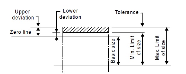
Limits of Size
Limits of size are two extreme permissible sizes between which the actual size exists. The maximum limit for a dimension is the largest permissible size, while the minimum limit for a dimension is the smallest permissible size. The maximum or minimum sizes represented by tolerances are called the limits. The basic sizes deviation and tolerances for both shaft and hole are illustrated in Fig. 1.
Zero Line and Deviation
In graphical representation of limits, straight line to which the deviations are of zero deviation and the represented of zero deviation are referred. The zero line is also known as line of zero deviation is generally drawn as horizontal line and the positive deviations are shown above this line and the negative deviations below it.
The algebraic difference between the actual or maximum size and the corresponding the basic size is called deviation. The deviations from the basic dimensions at the boundaries of the tolerance zone are called upper and lower deviations as depicted in Fig. 2.
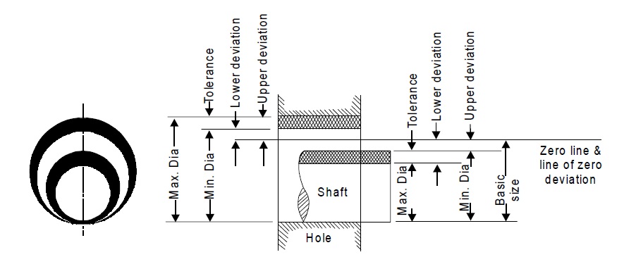
Fig. 2 Upper and lower deviations for both shaft and hole
Upper Deviation
It is the algebraic difference between the two maximum limit of any size of the part and the corresponding basic size.
Lower Deviation
It is the algebraic difference between the minimum limit of any size of the part and the corresponding basic size.
Mean Deviation
It is the arithmetical mean between the upper and lower deviations of any size of the part.
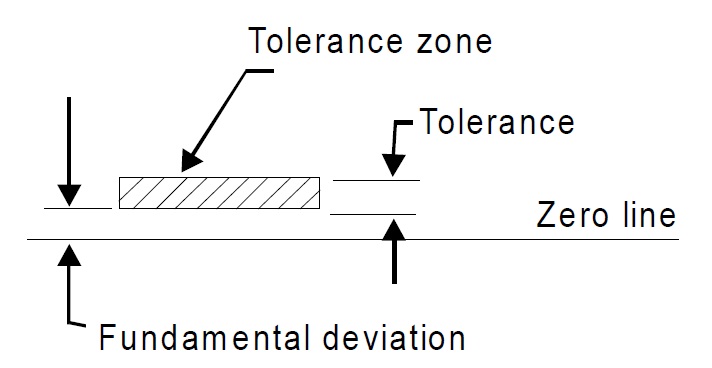
Fundamental Deviation
It is the one of the deviations, which is conventionally chosen to define the position of tolerance zone in relation to the zero line. The deviation of the tolerance band on shaft or hole away from the basic size is called the fundamental deviation. It is shown in Fig. 3.
The zero line shown is the line of zero deviation and represents the basic size. A zero line is a straight line to which the deviations are referred. For conventions, the zero line is drawn horizontally. The positive deviations are shown above and the negative deviations are shown below it.
Source from a textbook of manufacturing processes and workshop technology be Rajender Singh.


")


