

IC 555 timer is a well-known component in the electronic circles but what is not known to most of the people is the internal circuitry of the IC and the function of various pins present there in the IC. Let me tell you a fact about why 555 timer is called so, the timer got its name from the three 5 kilo-ohm resistor in series employed in the internal circuit of the IC.
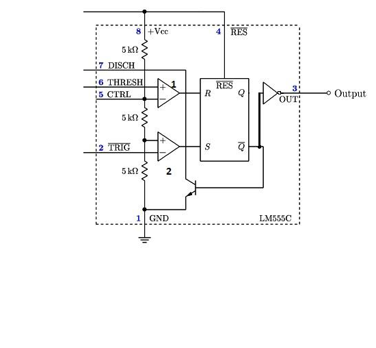
IC 555 timer is a one of the most widely used IC in electronics and is used in various electronic circuits for its robust and stable properties. It works as square-wave form generator with duty cycle varying from 50% to 100%, Oscillator and can also provide time delay in circuits. The 555 timer got its name from the three 5k ohm resistor connected in a voltage-divider pattern which is shown in the figure below. A simplified diagram of the internal circuit is given below for better understanding as the full internal circuit consists of over more than 16 resistors, 20 transistors, 2 diodes, a flip-flop and many other circuit components.
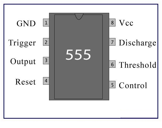
The 555 timer comes as 8 pin DIP (Dual In-line Package) device. There is also a 556 dual version of 555 timer which consists of two complete 555 timers in 14 DIP and a 558 quadruple timer which is consisting of four 555 timer in one IC and is available as a 16 pin DIP in the market.
Basics Concepts:
- Comparator: The Comparator are the basic electronic component which compares the two input voltages i.e. between the inverting (-) and the non-inverting (+) input and if the non-inverting input is more than the inverting input then the output of the comparator is high. Also the input resistance of an ideal comparator is infinite.
- Voltage Divider: As we know that the input resistance of the comparators is infinite hence the input voltage is divided equally between the three resistors. The value being Vin/3 across each resistor.
- Flip/Flop: Flip/Flop is a memory element of Digital-electronics. The output (Q) of the flip/flop is ‘high’ if the input at ‘S’ terminal is ‘high’ and ‘R’ is at ‘Low’ and the output (Q) is ‘low’ when the input at ‘S’ is ‘low’ and at ‘R’ is high.
Function of different Pins:-
- Ground: This pin is used to provide a zero voltage rail to the Integrated circuit to divide the supply potential between the three resistors shown in the diagram.
- Trigger: As we can see that the voltage at the non-inverting end of the comparator is Vin/3, so if the trigger input is used to set the output of the F/F to ‘high’ state by applying a voltage equal to or less than Vin/3 or any negative pulse, as the voltage at the non-inverting end of the comparator is Vin/3.
- Output: It is the output pin of the IC, connected to the Q’ (Q-bar) of the F/F with an inverter in between as show in the figure.
- Reset: This pin is used to reset the output of the F/F regardless of the initial condition of the F/F and also it is an active low Pin so it connected to ‘high’ state to avoid any noise interference, unless a reset operation is required. So most of the time it is connected to the Supply voltage as shown in the figure.
- Control Voltage: As we can see that the pin 5 is connected to the inverting input having a voltage level of (2/3) Vin. It is used to override the inverting voltage to change the width of the output signal irrespective of the RC timing network.
- Threshold: The pin is connected to the non-inverting input of the first comparator. The output of the comparator will be high when the threshold voltage will be more than (2/3) Vin thus resetting the output (Q) of the F/F from ‘high’ to ‘low’.
- Discharge: This pin is used to discharge the timing capacitors (capacitors involved in the external circuit to make the IC behave as a square wave generator) to ground when the output of Pin 3 is switched to ‘low’.
- Supply: This pin is used to provide the IC with the supply voltage for the functioning and carrying of the different operations to be fulfilled with the 555 timer.
Uses:-
The IC 55 timer is used in many circuits, for example One-shot pulse generator in Monostable mode as an Oscillator in Astable Mode or in Bistable mode to produce a flip/flop type action. It is also used in many types of other circuit for achievement of various purposes for instance Pulse Amplitude Modulatin (PAM), Pulse Width Modulation (PWM) etc.
More about these circuits will be explained in the later tutorials.


