

How to Receive SMS Using GSM Module with Arduino
[nextpage title=”Summary” ]In certain applications the microcontroller based systems has to be connected with the GSM network which will enable a user to control the system by sending messages or making a call. The advantage of using a GSM communication with a system or device is that the user can control the system wirelessly no matter how far it is kept compared to any other wireless communication, provided that both the user and the device should be in a cellular coverage area.
The mobile phones have built in GSM modules which then be used by the processor inside the phone to make a call, send or receive message or even connect with the GPRS network. When it comes to a microcontroller based system a separate GSM module is used rather than using a cell phone as such. There are GSM modules available which can do serial communication with microcontroller based systems. The communication is done by sending or receiving AT commands with the GSM module.This particular project demonstrates how to interface a GSM module and read and display SMS on the 16*2 LCD.
Any AVR microcontroller based board which follows the standard Arduino schematic and is flashed with the Arduino bootloader can be called an Arduino board. The Arduino is refered to as open source hardware and the Arduino IDE is also open source and anybody can contribute their libraries to the Arduino. All arduino boards should be compatible with the Arduino IDE which can be used to program the Arduino boards.
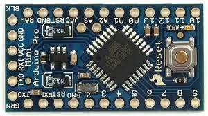
[/nextpage][nextpage title=”Description” ]The working of this project is explained based on the Arduino pro-mini board and the IDE version 1.0.3 for windows. The advantage of this board is that it comes in very small in size; any kind of connectors can be soldered on its periphery according to our requirements. It is very breadboard friendly and occupies very less space of a typical breadboard.
The image of the Arduino pro-mini board and the Arduino IDE are shown below:
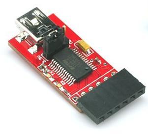
Since the Arduino pro-mini board has no circuitry for interfacing it with the serial port or the USB port of the PC, an external USB to TTL converter board is required to connect it with the PC. This hardware helps in programming the Arduino board and also helps in the serial communication with the USB port of the PC.
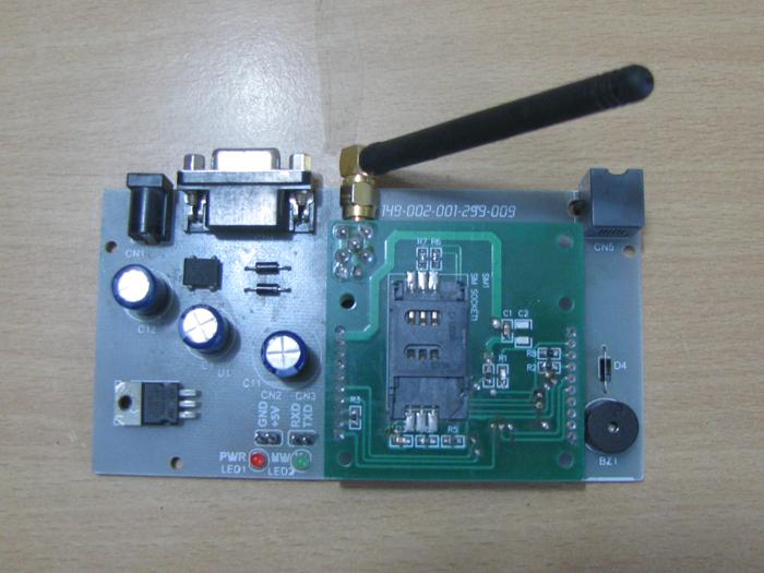
The GSM module used in this project is a SIM900 based module which can communicate with other devices using RS232 serial communication port. It works on 9V power supply and the image of the same is given below:
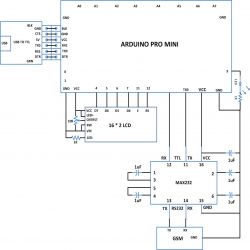
The GSM module is connected with the Arduino board using the serial communication port. Since the module has RS232 port and the Arduino pro-mini can communicate using TTL logic levels a max232 IC is used to make a bi-directional conversion between the RS232 and TTL logic levels. The Tx pin of the Arduino board is connected to the Rx pin of the GSM module through the max232 and the Rx pin of the Arduino is connected to the Tx pin of the GSM module using max232 itself.
GSM modules respond “OK” when it receives the command “AT” and it is the best way of check communication between the module and the microcontroller.
+CMGF – This command is used to set the SMS mode. Either text or PDU mode can be selected by assigning 1 or 0 in the command.
SYNTAX: AT+CMGF=<mode>
0: for PDU mode
1: for text mode
For example,
AT+CMGF=1
+CNMI- This AT command is used to specify how newly arrived SMS messages should be handled. It can be used to set the GSM/GPRS modem or mobile phone either to route a received SMS messages directly to the serial port, or to save them in message storage and then notify the host device by sending a string through the serial port.
SYNTAX: AT+CNMI=<mode>
For example to route the received message string to the serial port of the device, the code written for this project uses the following command;
AT+CNMI=2,2,0,0,0
Once a SMS is received the GSM module sends a long string to the Arduino board which consists of so many details regarding the message and also includes the original text. The code is written in such a way that it will wait till any character is received through the serial port and once starts receiving it will check for the occurrence of fourth ‘ ” ’ and write the rest of the characters directly into the 16*2 LCD. The characters after the fourth ‘ “ ’ in the received string will be the original text and the rest of the characters are ignored in the code using the following lines;
do
{
while ( !Serial.available() );
} while ( ‘”‘ != Serial.read() );
do
{
while ( !Serial.available() );
} while ( ‘”‘ != Serial.read() );
do
{
while ( !Serial.available() );
} while ( ‘”‘ != Serial.read() );
do
{
while ( !Serial.available() );
} while ( ‘”‘ != Serial.read() );
[/nextpage][nextpage title=”Circuit Diagram” ]
[/nextpage]


