

Gib and Cotter Joint

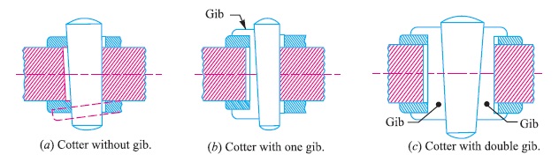
A gib and cotter joint is usually used in strap end (or big end) of a connecting rod as shown in Fig. 1. In such cases, when the cotter alone (i.e. without gib) is driven, the friction between its ends and the inside of the slots in the strap tends to cause the sides of the strap to spring open (or spread) outwards as shown dotted in Fig. 4 (a). In order to prevent this, gibs as shown in Fig. 4 (b) and (c), are used which hold together the ends of the strap.
Moreover, gibs provide a larger bearing surface for the cotter to slide on, due to the increased holding power. Thus, the tendency of cotter to slacken back owing to friction is considerably decreased. The jib, also, enables parallel holes to be used.
Notes :
1. When one gib is used, the cotter with one side tapered is provided and the gib is always on the outside as shown in Fig. 4 (b).
2. When two jibs are used, the cotter with both sides tapered is provided.
3. Sometimes to prevent loosening of cotter, a small set screw is used through the rod jamming against the cotter.
2. Design of Gib and Cotter Joint for Square Rods
Design of a Gib and Cotter Joint for Strap End of a Connecting Rod
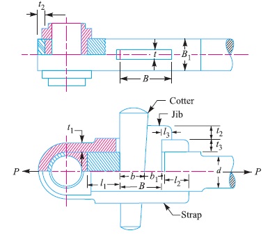
Consider a gib and cotter joint for strap end (or big end) of a connecting rod as shown in Fig. 5. The connecting rod is subjected to tensile and compressive loads.
Let P = Maximum thrust or pull in the connecting rod,
d = Diameter of the adjacent end of the round part of the rod,
B1 = Width of the strap,
B = Total width of gib and cotter,
t = Thickness of cotter,
t1 = Thickness of the strap at the thinnest part,
σt = Permissible tensile stress for the material of the strap, and
τ = Permissible shear stress for the material of the cotter and gib.
The width of strap ( B1) is generally taken equal to the diameter of the adjacent end of the round part of the rod ( d ). The other dimensions may be fixed as follows :
Thickness of cotter,
t = Width of strap / 4 = B1/4
Thickness of gib = Thickness of cotter (t)
Height (t2) and length of gib head (l3)
= Thickness of cotter (t)
In designing the gib and cotter joint for strap end of a connecting rod, the following modes of failure are considered.
1. Failure of the strap in tension
Assuming that no hole is provided for lubrication, the area that resists the failure of the strap due to tearing = 2 B1 × t1
∴ Tearing strength of the strap
= 2 B1 × t1 × σt
Equating this to the load (P), we get
P = 2 B1 × t1 × σt
From this equation, the thickness of the strap at the thinnest part (t1) may be obtained. When an oil hole is provided in the strap, then its weakening effect should be considered. The thickness of the strap at the cotter (t3) is increased such that the area of cross-section of the strap at the cotter hole is not less than the area of the strap at the thinnest part. In other words 2 t3 (B1 – t) = 2 t1 × B1
From this expression, the value of t3 may be obtained.
Note : This picture is given as additional information and is not a direct example of the current chapter.
2. Failure of the gib and cotter in shearing
Since the gib and cotter are in double shear, therefore area resisting failure
= 2 B × t
and resisting strength = 2 B × t × τ
Equating this to the load (P), we get
P = 2 B × t × τ
From this equation, the total width of gib and cotter (B) may be obtained. In the joint, as shown in Fig. 5, one gib is used, the proportions of which are
Width of gib,b1 =0.55 B ; and
width of cotter, b = 0.45 B
The other dimensions may be fixed as follows :
Thickness of the strap at the crown,
t4 = 1.15 t1 to 1.5 t1
l1 = 2 t1; and l2 = 2.5 t1
Reference A Textbook of Machine Design by R.S. Khurmi and J.K. Gupta


 of a connecting rod. In such cases, when the cotter.)