

Types of gears
[nextpage title=”Introduction” ]
Here we will discuss about types of gears, A gear or cogwheel is a rotating machine part having cut teeth, or cogs. Which mesh with another toothed part in order to transmit torque. In most cases with teeth on the one gear being of identical shape, and often also with that shape on the other gear. Two or more gears working in tandem are called a transmission. It can produce a mechanical advantage through a gear ratio and thus may be considered a simple machine. Geared devices can change the speed, torque, and direction of a power source. The most common situation is for a gear to mesh with another gear. However, a gear can also mesh with a non-rotating toothed part, called a rack. Thereby producing translation instead of rotation.
The gears in a transmission are analogous to the wheels in a crossed belt pulley system. An advantage of gears is that the teeth of a gear prevent slippage.
Gears are used in tons of mechanical devices. They do several important jobs. But most important. They provide a gear reduction in motorized equipment. This is key because, often, a small motor spinning very fast can provide enough power for a device. But not enough torque. For instance, an electric screwdriver has a very large gear reduction . Because it needs lots of torque to turn screws. But the motor only produces a small amount of torque at a high speed. With a gear reduction, the output speed can be reduced while the torque is increased.
When two gears mesh, and one gear is bigger than the other (even though the size of the teeth must match). A mechanical advantage is produced, with the rotational speeds and the torques of the two gears differing in an inverse relationship.
In transmissions which offer multiple gear ratios, such as bicycles, motorcycles, and cars, the term gear, as in first gear. It is refers to a gear ratio rather than an actual physical gear. The term is used to describe similar devices even when the gear ratio is continuous rather than discrete. When the device does not actually contain any gears, as in a continuously variable transmission.
[/nextpage]
[nextpage title=”Types of Gear” ]
TYPES OF GEARS
Different types of gear are Mention Below:
- Spur Gear
- Helical Gear
- Herringbone Gear
- Rack and Pinion
- Bevel Gear
- Spiral Bevel Gear
- Screw Gear
- Worm & Worm Wheel
- Miter Gear
- Internal Gear
Types of Gear
[/nextpage]
[nextpage title=”Shifting of Gears” ]
Shifting of gears
In some machines (e.g., automobiles) it is necessary to alter the gear ratio to suit the task, a process known as gear shifting or changing gear. There are several ways of shifting gears, for example:[sam id=”4″ codes=”true”]
- Manual transmission
- Automatic transmission
- Derailleur gears which are actually sprockets in combination with a roller chain
- Hub gears (also called epicyclic gearing or sun-and-planet gears)[/nextpage]
There are several outcomes of gear shifting in motor vehicles. In the case of vehicle noise emissions, there are higher sound levels emitted. When the vehicle is engaged in lower gears. The design life of the lower ratio gears is shorter, so cheaper gears may be used. Which tend to generate more noise due to smaller overlap ratio and a lower mesh stiffness etc. than the helical gears used for the high ratios. This fact has been used to analyze vehicle-generated sound since the late 1960s, and has been incorporated into the simulation of urban roadway noise and corresponding design of urban noise barriers along roadways.[sam id=”4″ codes=”true”]
[/nextpage]
[nextpage title=”Spur Gear” ]
1) Spur Gear-Parallel and co-planer shafts connected by gears are called spur gears. The arrangement is called spur gearing.
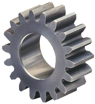
Spur gears have straight teeth and are parallel to the axis of the wheel. Spur gears are the most common type of gears. The advantages of spur gears are their simplicity in design, economy of manufacture and maintenance, and absence of end thrust. They impose only radial loads on the bearings.
Spur gears are known as slow speed gears. If noise is not a serious design problem, spur gears can be used at almost any speed.
[/nextpage]
[nextpage title=”Helical Gear” ]
2) Helical Gear-Helical gears have their teeth inclined to the axis of the shafts in the form of a helix, hence the name helical gears.
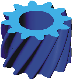
These gears are usually thought of as high speed gears. Helical gears can take higher loads than similarly sized spur gears. The motion of helical gears is smoother and quieter than the motion of spur gears.
Single helical gears impose both radial loads and thrust loads on their bearings and so require the use of thrust bearings. The angle of the helix on both the gear and the must be same in magnitude but opposite in direction, i.e., a right hand pinion meshes with a left hand gear.
[/nextpage]
[nextpage title=”Herringbone Gear” ]
3) Herringbone Gear – Herringbone gears resemble two helical gears that have been placed side by side. They are often referred to as “double helicals”. In the double helical gears arrangement, the thrusts are counter-balanced. In such double helical gears there is no thrust loading on the bearings.

Herringbone Gear
[/nextpage]
[nextpage title=”Bevel/Miter Gear” ]
4) Bevel/Miter Gear-Intersecting but coplanar shafts connected by gears are called bevel gears. This arrangement is known as bevel gearing. Straight bevel gears can be used on shafts at any angle, but right angle is the most common. Bevel Gears have conical blanks. The teeth of straight bevel gears are tapered in both thickness and tooth height.
Spiral Bevel gears: In these Spiral Bevel gears, the teeth are oblique. Spiral Bevel gears are quieter and can take up more load as compared to straight bevel gears.
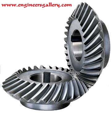
Zero Bevel gear: Zero Bevel gears are similar to straight bevel gears, but their teeth are curved lengthwise. These curved teeth of zero bevel gears are arranged in a manner that the effective spiral angle is zero.
[/nextpage]
[nextpage title=”Worm Gear” ]
5) Worm Gear– Worm gears are used to transmit power at 90° and where high reductions are required. The axes of worm gears shafts cross in space. The shafts of worm gears lie in parallel planes and may be skewed at any angle between zero and a right angle.In worm gears, one gear has screw threads. Due to this, worm gears are quiet, vibration free and give a smooth output.Worm gears and worm gear shafts are almost invariably at right angles.
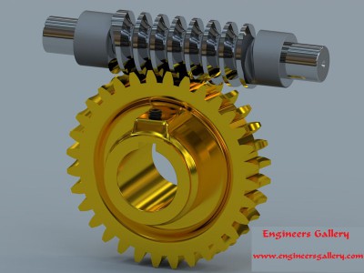
Worm Gear
[/nextpage]
[nextpage title=”Rack and Pinion” ]
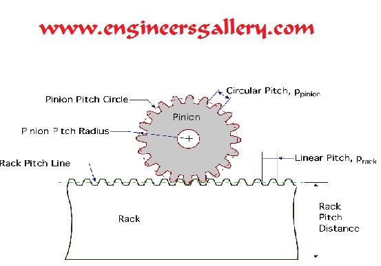
6) Rack and Pinion– A rack is a toothed bar or rod that can be thought of as a sector gear with an infinitely large radius of curvature. Torque can be converted to linear force by meshing a rack with a pinion: the pinion turns; the rack moves in a straight line. Such a mechanism is used in automobiles to convert the rotation of the steering wheel into the left-to-right motion of the tie rod(s). Racks also feature in the theory of gear geometry, where, for instance, the tooth shape of an interchangeable set of gears may be specified for the rack (infinite radius), and the tooth shapes for gears of particular actual radii then derived from that. The rack and pinion gear type is employed in a rack railway.
[/nextpage][nextpage title=”Internal & External Gear” ]
7) Internal & External Gear– An external gear is one with the teeth formed on the outer surface of a cylinder or cone. Conversely, an internal gear is one with the teeth formed on the inner surface of a cylinder or cone. For bevel gears, an internal gear is one with the pitch angle exceeding 90 degrees. Internal gears do not cause direction reversal.
[/nextpage]
[nextpage title=”Face Gears” ]
8) Face Gears– Face gears transmit power at (usually) right angles in a circular motion. Face gears are not very common in industrial application.
[/nextpage][nextpage title=”Sprockets” ]
9) Sprockets–Sprockets are used to run chains or belts. They are typically used in conveyor systems.
[/nextpage]
For more detail on Different types of gears, visit our gear section.


