

Epicyclic Gear Train
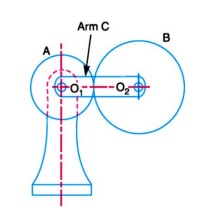
We have already discussed that in an epicyclic gear train, the axes of the shafts, over which the gears are mounted, may move relative to a fixed axis. A simple epicyclic gear train is shown in Fig. 13.6, where a gear A and the arm C have a
common axis at O1 about which they can rotate. The gear B meshes with gear A and has its axis on the arm at O2, about which the gear B can rotate. If the arm is fixed, the gear train is simple and gear A can drive gear B or vice- versa, but if gear A is fixed and the arm is rotated about the axis of gear A (i.e. O1), then the gear B is forced to rotate upon and around gear A. Such a motion is called epicyclic and the gear trains arranged in such a manner that one or more of their members move upon and around another member is known as epicyclic gear trains (epicyclic means upon and cyclic means around). The epicyclic gear trains may be simple or compound. The epicyclic gear trains are useful for transmitting high velocity ratios with gears of moderate size in a comparatively lesser space. The epicyclic gear trains are used in the back gear of lathe, differential gears of the automobiles, hoists, pulley blocks, wrist watches etc.
Fig. 1 Epicyclic Gear Train
Velocity Ratios of Epicyclic Gear Train:
The following two methods may be used for finding out the velocity ratio of an epicyclic gear train. 1. Tabular method, and 2. Algebraic method.These methods are discussed, in detail, as follows:
1. Tabular method.Consider an epicyclic gear train as shown in Fig. 1.
Let,TA = Number of teeth on gear A, and
TB = Number of teeth on gear B.
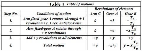
First of all, let us suppose that the arm is fixed. Therefore the axes of both the gears are also fixed relative to each other. When the gear A makes one revolution anticlockwise, the gear B will make TA / TB revolutions, clockwise. Assuming the anticlockwise rotation as positive and clockwise as negative, we may say that when gear A makes + 1 revolution, then the gear B will make (– TA / TB) revolutions. This
statement of relative motion is entered in the first row of the table (see Table 1.).Secondly, if the gear A makes + x revolutions, then the gear B will make ( – x × TA / TB ) revolutions. This statement is entered in the second row of the table. In other words, multiply the each motion (entered in the first row) by x.
Thirdly, each element of an epicyclic train is given + y revolutions and entered in the third row. Finally, the motion of each element of the gear train is added up and entered in the fourth row.


