

Design of Turnbuckle :
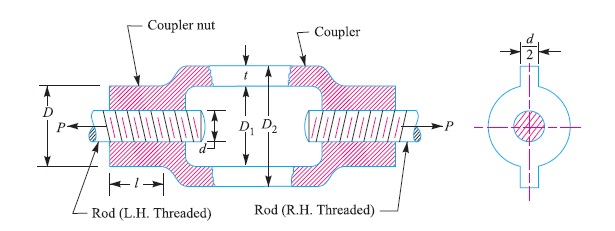
Consider a turnbuckle, subjected to an axial load P, as shown in Fig. 1. Due to this load, the threaded rod will be subjected to tensile stress whose magnitude is given by
σt = P / A
= P / [{π (dc)^2} / 4]
where dc = Core diameter of the threaded rod.
In order to drive the rods, the torque required is given by
T = P tan (α + φ) dp/2
where α = Helix angle,
tan φ = Coefficient of friction between the threaded rod and the coupler nut, and
dp = Pitch diameter or mean diameter of the threaded rod.
∴ Shear stress produced by the torque,
τ = (T × dp)/ (2 × J)
= [{P tan (α + φ) dp/2} × dp] / [{2 × π (dp)^4} / 32]
= [P tan (α + φ) × 8] / [π (dp)^2]
= 8P [(tan α + tan α) / (1 – tan α tan α)]/ [π (dp)^2]
The usual values of tan α, tan φ and dp are as follows :
tan α = 0.03, tan φ = 0.2, and dp = 1.08 dc
Substituting these values in the above expression, we get
τ = 8P [(0.03 + 0.2) / (1 – 0.03 × 0.2)]/ [π (1.08 dc)^2]
= 8P / 4π (dc)^2
= P / 2A
= σt / 2
Since the threaded rod is subjected to tensile stress as well as shear stress, therefore maximum principal stress,
σt (max) = (σt / 2) + {[{σt^2 + 4τ^2}^0.5]/2}
= (σt / 2) + {[{σt^2 + σt^2}^0.5]/2} (‘.’ τ = σt / 2)
= 0.5 σt + 0.707 σt
= 1.207 σt
= 1.207 P / A
Giving a margin for higher coefficient of friction, the maximum principal stress may be taken as 1.3 times the normal stress. Therefore for designing a threaded section, we shall take the design load as 1.3 times the normal load, i.e. Design load, Pd = 1.3 P
The following procedure may be adopted in designing a turn-buckle :
1. Diameter of the rods
The diameter of the rods (d) may be obtained by considering the tearing of the threads of the rods at their roots. We know that
Tearing resistance of the threads of the rod
= π (dc)^2 σt / 4
Equating the design load (Pd) to the tearing resistance of the threads, we have
Pd = π (dc)^2 σt / 4
where dc = Core diameter of the threads of the rod, and
σt = Permissible tensile stress for the material of the rod.
From the above expression, the core diameter of the threads may be obtained. The nominal diameter of the threads (or diameter of the rod) may be found from Table 11.1, corresponding to the core diameter, assuming coarse threads.
2. Length of the coupler nut
The length of the coupler nut (l) is obtained by considering the shearing of the threads at their roots in the coupler nut. We know that
Shearing resistance of the threads of the coupler nut
= (π dc × l) τ
where τ = Shear stress for the material of the coupler nut.
Equating the design load to the shearing resistance of the threads in the coupler nut, we have
Pd = (π dc × l ) τ
From this expression, the value of l may be calculated. In actual practice, the length of coupler nut ( l ) is taken d to 1.25 d for steel nuts and 1.5 d to 2 d for cast iron and softer material nut. The length of the coupler nut may also be checked for crushing of threads. We know that
Crushing resistance of the threads in the coupler nut
= (π/4) (d^2 – dc^2) (n) (l) (σc)
where σc = Crushing stress induced in the coupler nut, and
n = Number of threads per mm length.
Equating the design load to the crushing resistance of the threads, we have
Pd = = (π/4) (d^2 – dc^2) (n) (l) (σc)
From this expression, the induced σc may be checked.
3. Outside diameter of the coupler nut
The outside diameter of the coupler nut (D) may be obtained by considering the tearing at the coupler nut. We know that
Tearing resistance at the coupler nut
= (π/4) (D^2 – d^2) (σt)
where σt = Permissible tensile stress for the material of the coupler nut.
Equating the axial load to the tearing resistance at the coupler nut, we have
P = (π/4) (D^2 – d^2) (σt)
From this expression, the value of D may be calculated. In actual practice, the diameter of the coupler nut (D) is taken from 1.25 d to 1.5 d.
4. Outside diameter of the coupler
The outside diameter of the coupler (D2) may be obtained by considering the tearing of the coupler. We know that
Tearing resistance of the coupler
= (π/4) {(D2)^2 – (D1)^2} (σt)
where D1 = Inside diameter of the coupler. It is generally taken as (d + 6 mm), and
σt = Permissible tensile stress for the material of the coupler.
Equating the axial load to the tearing resistance of the coupler, we have
P = (π/4) {(D2)^2 – (D1)^2} (σt)
From this expression, the value of D2 may be calculated. In actual practice, the outside diameter of the coupler (D2) is taken as 1.5 d to 1.7 d. If the section of the coupler is to be made hexagonal or rectangular to fit the spanner, it may be circumscribed over the circle of outside diameter D2.
5. The length of the coupler between the nuts (L) depends upon the amount of adjustment required. It is usually taken as 6 d.
6. The thickness of the coupler is usually taken as t = 0.75 d, and thickness of the coupler nut, t1 = 0.5 d.
Reference A Textbook of a Machine Design by R.S. Khurmi and J.K. Gupta


")


