

Design of Flywheel Arms
The cross-section of the arms is usually elliptical with major axis as twice the minor axis, as shown in Fig. 1, and it is designed for the maximum bending stress.
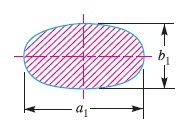
Let a1 = Major axis, and
b1 = Minor axis.
∴ Section modulus,
Z = π/32 × b1 (a1)^2 ……(i)
We know that maximum bending moment,
M = T ( R – r) / R n
∴ Maximum bending stress,
σb = M / Z = T ( R – r) / R n Z ……(ii)
Assuming a1 = 2 b1, the dimensions of the arms may be obtained
from equations (i) and (ii).
Notes:
1. The arms of the flywheel have a taper from the hub to the rim. The
taper is about 20 mm per metre length of the arm for the major axis and 10 mm per metre length for the minor axis.
2. The number of arms are usually 6. Sometimes the arms may be 8, 10 or 12 for very large size flywheels.
3. The arms may be curved or straight. But straight arms are easy to cast and are lighter.
4. Since arms are subjected to reversal of stresses, therefore a minimum factor of safety 8 should be used. In some cases like punching machines amd machines subjected to severe shock, a factor of safety 15 may be used.
5. The smaller flywheels (less than 600 mm diameter) are not provided with arms. They are made web type with holes in the web to facilitate handling.
Reference A Textbook of Machine Design by R.S. Khurmi and J.K.Gupta


