

Design of Flange Coupling
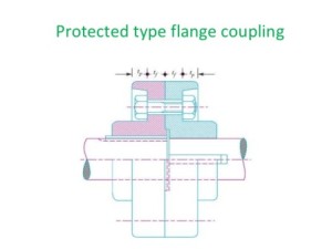
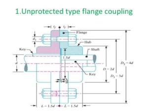
Consider a flange coupling as shown in Fig. 1 and Fig. 2.
Let d = Diameter of shaft or inner diameter of hub,
D = Outer diameter of hub,
d1 = Nominal or outside diameter of bolt,
D1 = Diameter of bolt circle,
n = Number of bolts,
tf = Thickness of flange,
τs, τb and τk = Allowable shear stress for shaft, bolt and key material respectively
τc = Allowable shear stress for the flange material i.e. cast iron,
σcb, and σck = Allowable crushing stress for bolt and key material respectively.
The flange coupling is designed as discussed below :
[nextpage title=”1. Design for hub” ]
1. Design for hub
The hub is designed by considering it as a hollow shaft, transmitting the same torque (T) as that of a solid shaft.
T = π/16 × τc { (D^4 – d^4) / D }
The outer diameter of hub is usually taken as twice the diameter of shaft. Therefore from the above relation, the induced shearing stress in the hub may be checked.
The length of hub (L) is taken as 1.5 d.
[/nextpage]
[nextpage title=”2. Design for key” ]
2. Design for key
The key is designed with usual proportions and then checked for shearing and crushing stresses.
The material of key is usually the same as that of shaft. The length of key is taken equal to the length of hub.
[/nextpage]
[nextpage title=”3. Design for flange” ]
3. Design for flange
The flange at the junction of the hub is under shear while transmitting the torque. Therefore, the troque transmitted,
T = Circumference of hub × Thickness of flange × Shear stress of flange × Radius of hub
= π D × tf × τc × D/2 = {(πD^2) / 2} × τc × tf
The thickness of flange is usually taken as half the diameter of shaft. Therefore from the above relation, the induced shearing stress in the flange may be checked.
[/nextpage]
[nextpage title=”4. Design for bolts” ]
4. Design for bolts
The bolts are subjected to shear stress due to the torque transmitted. The number of bolts (n) depends upon the diameter of shaft and the pitch circle diameter of bolts (D1) is taken as 3 d. We know that
Load on each bolt = π/4 d1^2 τb
∴ Total load on all the bolts = π/4 d1^2 τb × n
and torque transmitted, T = π/4 d1^2 τb × n × D1/2
From this equation, the diameter of bolt (d1) may be obtained. Now the diameter of bolt may be checked in crushing.
We know that area resisting crushing of all the bolts
= n × d1 × tf
and crushing strength of all the bolts
= (n × d1 × tf ) σcb
∴ Torque, T = (n × d1 × tf × σcb ) D1/2
From this equation, the induced crushing stress in the bolts may be checked.
[/nextpage]
Reference by A Textbook of a Machine Design by R. S. Khurmi and J. K. Gupta


