

Design of Cotter Joint to Connect Piston Rod and Cross head :
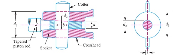
The cotter joint to connect piston rod and cross head is shown in Fig. 1. In such a type of joint, the piston rod is tapered in order to resist the thrust instead of being provided with a collar for the purpose. The taper may be from 1 in 24 to 1 in 12.
Let d = Diameter of parallel part of the piston rod,
d1 = Diameter at tapered end of the piston,
d2 = Diameter of piston rod at the cotter,
d3 = Diameter of socket through the cotter hole,
b = Width of cotter at the centre,
t = Thickness of cotter,
σt , τ and σc = Permissible stresses in tension, shear and crushing
respectively.
We know that maximum load on the piston,
P = [π × D^2 × p] /4
where D = Diameter of the piston, and
p = Effective steam pressure on the piston.
Let us now consider the various failures of the joint as discussed below :
1. Failure of piston rod in tension at cotter
The piston rod may fail in tension at cotter due to the maximum load on the piston. We know that area resisting tearing at the cotter
= [π (d2)^2 / 4] – [d2 × t]
∴ Tearing strength of the piston rod at the cotter
= {[π (d2)^2 / 4] – [d2 × t]} σt
Equating this to maximum load (P), we have
P = {[π (d2)^2 / 4] – [d2 × t]} σt
From this equation, the diameter of piston rod at the cotter (d2) may be determined.
Note:
The thickness of cotter (t) is taken as 0.3 d2.
2. Failure of cotter in shear
Since the cotter is in double shear, therefore shearing area of the cotter
= 2 b × t
and shearing strength of the cotter
= 2 b × t × τ
Equating this to maximum load (P), we have
P = 2 b × t × τ
From this equation, width of cotter (b) is obtained.
3. Failure of the socket in tension at cotter
We know that area that resists tearing of socket at cotter
= {π/4 × [(d3)^2 – (d2)^2]} – [d3 – d2]
and tearing strength of socket at cotter
= [{π/4 × [(d3)^2 – (d2)^2]} – [d3 – d2]] σt
Equating this to maximum load (P), we have
P = [{π/4 × [(d3)^2 – (d2)^2]} – [d3 – d2]] σt
From this equation, diameter of socket (d3) is obtained.
4. Failure of socket in crushing
We know that area that resists crushing of socket
= (d3 – d2) t
and crushing strength of socket
= (d3 – d2) t × σc
Equating this to maximum load (P), we have
P = (d3 – d2) t × σc
From this equation, the induced crushing stress in the socket may be checked.
The length of the tapered portion of the piston rod (L) is taken as 2.2 d2. The diameter of the parallel part of the piston rod (d) and diameter of the piston rod at the tapered end (d1) may be obtained as follows :
d = d2 + {(L/2) × taper} ; and d1 = d2– {(L/2) × taper}
Note:
The taper on the piston rod is usually taken as 1 in 20.
Reference A Textbook of Machine Design by R.S. Khurmi and J.K. Gupta


