

In the last tutorial on CRO I gave you a detailed idea about the various components of an Oscilloscope concerned with the positioning and magnification of an input signal and the role of probes was also explained. Now since you have been acquainted with the primary knobs of a Cathode Ray Oscilloscope it’s time to dive deeper and to know more about the other knobs which are helpful in further observation of a signal.
On/Off: This is required to turn the CRO on or off as per the requirement.
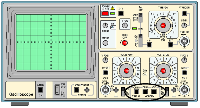
Channel Select: As we know most of the CRO can work simultaneously with two signals and thus there is a toggle switch present in the controls regarding the selection, i.e., if both the channels are used or only one is used. So, selection must be done accordingly. If both the channels are used the selection should be ‘Dual’ and if only one channel is used it should be either ‘channel 1’ or ‘channel 2’ depending on the connection.
Trigger Hold-Off: The trace in a CRO is performed by the sweeping of electrons for a small period of time on the phosphorous screen by the voltage generated due to the signal. This voltage is known as sweep voltage. When the ‘sweep’ is completed the voltage returns to its original value and thus forcing the beam of electrons to move back. This process is called ‘retrace’, when the retrace is completed again sweep starts. Hold-Off determines the time that tends to pass between ‘retrace’ and ‘sweep’. Initially it is set to zero, but to avoid the certain peaks and noises in the signal the sweep time can be increased to obtain a stable signal at the display.
[sam id=”5″ codes=”true”]
AC/DC/GD: This is a toggle switch to tell the CRO about the filtering of the i/p signal channel. This is present one for each channel.
- AC (Alternating Current Coupling): If the switch is at AC then the signal will go through a RC-filter to remove its DC components.
- DC (Direct Current Coupling): If the switch is at DC position then the signal will not go through a RC-filter and the DC components will persist in the signal.
- GD (Ground): If the switch is at the GD position then the input signal is shorted and thus a horizontal line is seen in the display symbolizing no potential difference between ground and input signal.
Focus: This rotating knob is used to improve the sharpness of an image of the signal on the screen by adjusting the focus of the electronic beam. Thus, it helps in taking the proper measurements and to study the correct shape of the signal by removing the blurriness of the signal.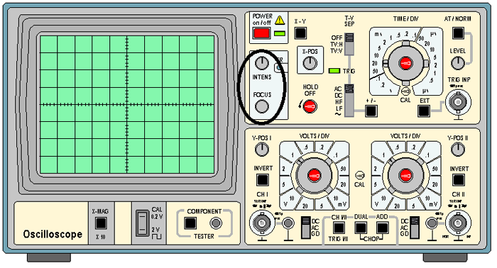
Intensity: This knob is used to increase the intensity of the input signal for better examination of the displayed output on the screen. There is a common misconception regarding this knob to be a brightness control feature but it is not so, this increases the number of electrons in the beam so that more and more electrons collide the phosphorus screen for better view of the applied input signal. This knob is marked as ‘Intens’ on the CRO.
+/- : This determines if the signal is triggered during the positive flank or the negative flank. Now, the many of you must be wondering ‘what is triggering?’, it is the synchronization of the horizontal sweep of the CRO with the proper point of the signal. If the button is on descending slope of the signal is used while triggering otherwise the ascending slope of the signal is used.
At/Norm.: Using this button you can select between Automatic triggering (At.) and manual triggering level selection.
Level: When the triggering is set to manual mode this wheel is used to set the level of manual triggering, the +/- button will make sure ascending level triggering or descending level triggering is used.
Ext.: This button is used when the timing of the CRO is not determined by the input waveform but from some another external waveform. There is an input connector beside the button where the external input is connected for the display of the waveform. 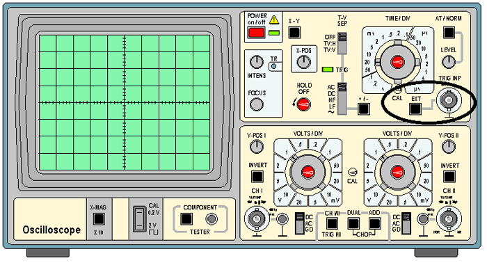


