

How to create custom characters on 16×2 LCD using 8051 microcontroller (AT89C51)
SUMMARY:
The commonly used 16×2 LCD can also display custom made characters besides numbers, alphabets & special characters. Any character can be made to appear on a 5×8 pixel matrix element without knowledge of its ASCII value. The idea explained here demonstrates the principle and operation of a simple LCD custom character display using 8051 microcontroller (AT89C51)
[visitor]
[/visitor]
DESCRIPTION:
When the ASCII code for any character, say ‘A’, is sent to be displayed on LCD module, the module’s controller looks up the appropriate 5×8-pixel pattern in ROM (read-only memory) and displays that pattern on the LCD. There are 8 symbol locations where a custom character can be stored as shown in the following right table. These locations will have a particular bitmap layout corresponding to the custom character. To display an arrow sign, the bitmap values are mapped to a base address location, say 64 (ASCII code 0).
The symbol locations with their base addresses are given below:
| ASCII Code | Base Address |
| 0 | 64 |
| 1 | 72 |
| 2 | 80 |
| 3 | 88 |
| 4 | 96 |
| 5 | 104 |
| 6 | 112 |
| 7 | 120 |
This is achieved by first sending the address location (64) to LCD command register. Next, the bitmap values (0, 4, 2, 31, 2, 4, 0, 0) are sent to the LCD data register. Now the arrow sign gets stored at the first address. Now whenever this symbol is to be displayed, its location needs to be sent to the command register of LCD.
There’s a 64-byte hunk of RAM (random-access memory) that the LCD controller uses in the same way as character-generator (CG) ROM. When the controller receives an ASCII code in the range that’s mapped to the CG RAM, it uses the bit patterns stored there to display a pattern on the LCD. The concept here lies in the fact one can write to the CG RAM, thereby defining one’s own graphic symbols. Each byte of CG RAM is mapped to a five-bit horizontal row of pixels, and LCD characters are typically eight rows high, so 64 bytes of CG RAM is enough to define eight custom characters. These characters correspond to ASCII codes 0 through 7. When an LCD is first powered up, CG RAM contains random garbage bits. If necessary, CG RAM may be cleared by writing 00 into each CG RAM cell.
Writing to CG RAM
Writing to CG RAM is a lot like moving the cursor to a particular position on the display and displaying characters at that new location. The steps involved are:
- Set RS (Register Select) and R/W (Read/Write) pins of the LCD to initialize the LCD to accept instructions
- Set the CG RAM address by sending an instruction byte from 64 to 127 (locations 0-63 in CG RAM).
- Switch to Data Mode by changing the setting of RS pin
- Send bytes with the bit patterns for your symbol(s). The LCD controller automatically increments CG RAM addresses, in the same way as it increments cursor positions on the display.
- To leave CG RAM, switch to Command Mode to set address counter to a valid display address (e.g. 128, 1st character of 1st line); the clear-screen instruction (byte 1); or the home instruction (byte 2). Now bytes are once again being written to the visible portion of the display.
- To display the defined custom character print ASCII codes 0 through 7.
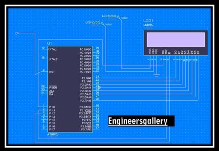
In the circuit, output of microcontroller AT89C51 (from port P2) goes to data pins of LCD numbered 7-14. The control pins RS (pin4), R/W (pin5) and EN (pin6) are connected to the pins 0, 1 and 6 of port P3 of the controller (P3^0, P3^1 & P3^6, respectively).
[visitor]
⇒ Subscribe to view Code & Circuit Diagram (Free Registration )
[/visitor][member]
[message_box title=”Program” color=”yellow”]
//Program to create and display custom characters smilies, heart, musical note symbol
#include<reg51.h>
sfr lcd_data_pin=0xA0;
sbit rs=P3^0; //Register select pin
sbit rw=P3^1; // Read write pin
sbit en=P3^6; //Enable pin
void delay(unsigned int count) // Function to provide time delay in msec.
{
int i,j;
for(i=0;i<count;i++)
for(j=0;j<1275;j++);
}
void lcd_command(unsigned char comm) //Function to send commands to LCD.
{
lcd_data_pin=comm;
en=1;
rs=0;
rw=0;
delay(1);
en=0;
}
void lcd_data(unsigned char disp) //Function to send data to LCD
{
lcd_data_pin=disp;
en=1;
rs=1;
rw=0;
delay(1);
en=0;
}
void lcd_ini() //Function to initialize the LCD
{
lcd_command(0x38);
delay(2);
lcd_command(0x0F);
delay(2);
lcd_command(0x82); //Set cursor to blink at line 1 positon 2
delay(2);
}
void character()
{
lcd_command(64); //Address where values of the first custom character is stored
lcd_data(0);
lcd_data(10);
lcd_data(21);
lcd_data(17);
lcd_data(10);
lcd_data(4);
lcd_data(0);
lcd_data(0);
lcd_command(0xC0); //Address of the location where the character is to be displayed
lcd_data(0); // Displaying the character created at address 0x64
delay(10);
lcd_command(72);
lcd_data(0);
lcd_data(0);
lcd_data(0);
lcd_data(10);
lcd_data(0);
lcd_data(4);
lcd_data(17);
lcd_data(14);
lcd_command(0x80);
lcd_data(1);
delay(10);
lcd_command(80);
lcd_data(0);
lcd_data(0);
lcd_data(10);
lcd_data(0);
lcd_data(4);
lcd_data(0);
lcd_data(14);
lcd_data(17);
lcd_command(0x82);
lcd_data(2);
delay(10);
lcd_command(88);
lcd_data(1);
lcd_data(3);
lcd_data(5);
lcd_data(9);
lcd_data(9);
lcd_data(11);
lcd_data(27);
lcd_data(24);
lcd_command(0x84);
lcd_data(3);
delay(10);
lcd_command(96);
lcd_data(0);
lcd_data(10);
lcd_data(0);
lcd_data(31);
lcd_data(17);
lcd_data(14);
lcd_data(0);
lcd_data(0);
lcd_command(0x86);
lcd_data(4);
delay(10);
lcd_command(104);
lcd_data(10);
lcd_data(0);
lcd_data(4);
lcd_data(0);
lcd_data(14);
lcd_data(17);
lcd_data(17);
lcd_data(14);
lcd_command(0xC2);
lcd_data(5);
delay(10);
lcd_command(112);
lcd_data(0);
lcd_data(10);
lcd_data(0);
lcd_data(0);
lcd_data(4);
lcd_data(0);
lcd_data(31);
lcd_data(0);
lcd_command(0xC4);
lcd_data(6);
delay(10);
lcd_command(120);
lcd_data(0);
lcd_data(17);
lcd_data(10);
lcd_data(17);
lcd_data(4);
lcd_data(0);
lcd_data(14);
lcd_data(17);
lcd_command(0xC6);
lcd_data(7);
delay(10);
}
void main()
{
lcd_ini();
character();
}
[/message_box]
[/member]


