

How to control GPIO with SCRATCH
Whilst the Raspberry Pi is a great tool for the creation of software, using languages such as Scratch, Python, C etc., the best way to make it really come alive and to add even more enjoyment to this cheap, credit card sized computer is to start playing around with hardware hacking and physical computing. This involves using the Raspberry Pi to control things like LEDs and respond to switches and sensors. More often than not it also includes knowledge and learning of both hardware and software in a very interesting practical environment – not just coding for the sake of coding but, for example, creating robots and programming them to do cool things!
This article is based on a post on the Cymplecy blog by Simon Walters (wp.me/p2C0q1-27), a primary school ICT teaching assistant and general Scratch guru!
Minimum Requirements – a Raspberry Pi with Raspbian installed and a working internet connection, a breadboard, some Light Emitting Diodes (LEDs), some resistors and some wire connectors. Total cost £5-£10 (not including the Pi).
How to get a Rapsberry Pi to control the GPIO Pins from Scratch
Your Raspberry Pi needs to be connected to the internet to install the software but internet is not needed to run Scratch GPIO. Copy the text below (starting at sudo and ending at gpio.sh) and paste that into an LX Terminal window and run it to download the installer:
[message_box title="" color="red"]sudo wget db.tt/jCIVXBJE -O /boot/install_scratch_gpio.sh
[/message_box]
And then type, and run:
[message_box title="" color="red"]sudo /boot/install_scratch_gpio.sh[/message_box]
This will install all the necessary extra software and some simple examples.
(If you do not have internet on your Pi then put your SD card into a card reader and try using your browser to right-click and save the script direct to your SD card and then put it back into your Pi and run the second instruction)
Connecting Components Up
Extreme care should be taken when connecting hardware to the GPIO pins as it can damage your Pi – only do this if you’re confident of your ability to follow these instructions correctly. At a minimum you should get a breadboard and use some female-male 0.1 leads (available from RS/CPC or your local Maplin). Check out some GPIO pin guides to make sure you know what pins do what.
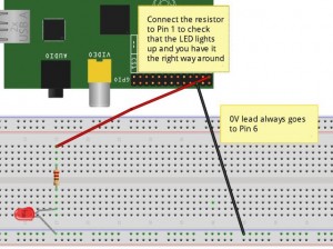
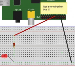 Fig 1. Fig 2.
As in Figure 1 above, wire up Pin 1 (3.3V) to (at least) a 330ohm resistor – connect that resistor to the long lead (this is the positive lead) of an LED and then connect the other end of the LED to Pin 6 (Ground). This should cause the LED to light up. If it doesn’t work try reversing your LED, as you probably have the polarities reversed. Once working, you can now move the red (or whatever colour you have used) lead from Pin 1 to Pin 11, as in Figure 2 above.
You should now run the special Scratch icon (Scratch GPIO) on your desktop. This is actually a completely normal version of Scratch, it just runs a little Python background program to allow Scratch to talk to the GPIO. If you have any Python programs accessing the GPIO running already this could cause your Pi to crash when opening Scratch GPIO. To avoid this, open an LX Terminal window and run: sudo killall python
To test out the GPIO control in Scratch, click File>Open and select blink11 from /home/pi/Scratch. Once the program has loaded, click on the Green Flag and your LED should now blink on for 1 second and off for 2 seconds – see troubleshooting on the Cymplecy blog if this doesn’t happen.


