

INTRODUCTION:
Here is a Hobby Circuit for electronics hobbyists that can switch on & off a light, Fan, Radio etc., by the sound of clap. The sound of clap is received by a small microphone that is shown biased by resistor R1 in the circuit. The microphone changes sound wave in to electrical wave, which is further amplified by Q1. Transistor Q1 is used as common emitter circuit to amplify weak signals received by the microphone. Amplified output from the collector of transistor Q1 is feed to the Bistable Multivibrator circuit also known as flip-flop circuit. Flip flop circuit is made by using two Transistor, in our circuit Q2&Q3. In a flip-flop circuit, at a time only one transistor conduct and other cutoff and when it gets a trigger pulse from outside source then first transistor is cutoff and 2nd transistor conducts, thus output of transistor is either logic-0 or logic-1 and it remains in one state 0 or 1 until it gets trigger pulse from outer source.
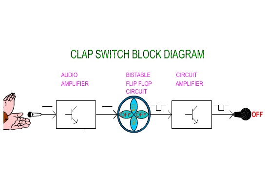
The pulse of clap, which is a trigger for flip-flop makes changes to the output state that is complementary (reverse). Output of flip-flop, which is in the low current form is unable to drive relay so we have used a current amplifier circuit by using Q4 that is a common emitter circuit. Output of Q4 is connected to a Relay (Electromagnetic switch) which works like a mechanical switch and it becomes easy for connecting other electrical appliance.
The relay contact is connected to the power line and hence turns on/off any electrical appliance connected all the way through relay.
 Circuit Diagram of clap Switch
Clap Switch Part List:-
R1=15KΩ, R5,R6=1.5KΩ
R2,R11,R12=2.2MΩ, R13=2.2KΩ
R3=270KΩ, R4=3.3KΩ
R7,R8=10KΩ, R9,R10=27KΩ
Capacitors
C1=1000µf/16v
C2=.01µf,C3,C4=.047µf
Semi Conductors
Q1,Q2,Q3= BC548
D2,D3,D4= IN 4148
D1,D5=IN 4007, Q4=BC368
Misc
T1=12v/500mA Transformer
Mic= Condenser Microphone
K1= 12V Relay, B1= Bulb or Load


